Examine the photos and plot the properties stated in the question. All programming languages are acceptable. Necessary explanations are provided at the beginning of the file.


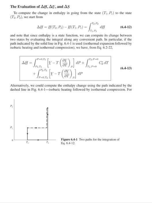
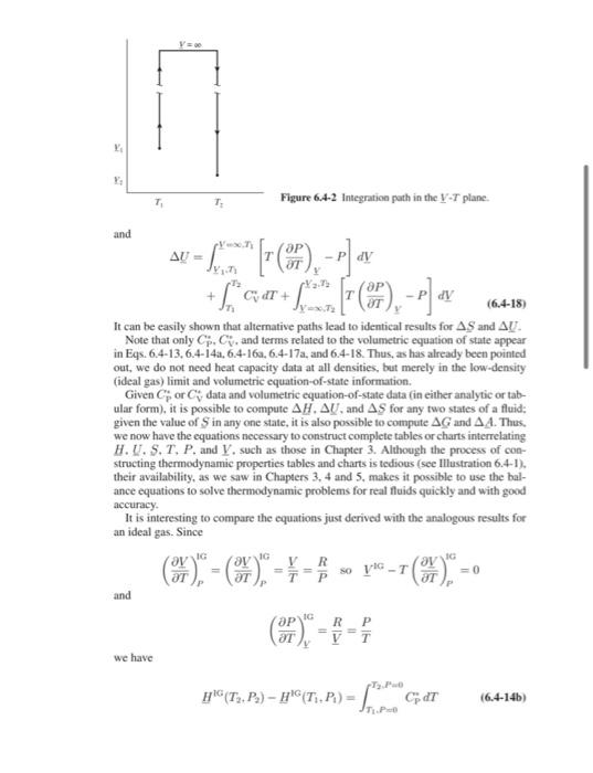
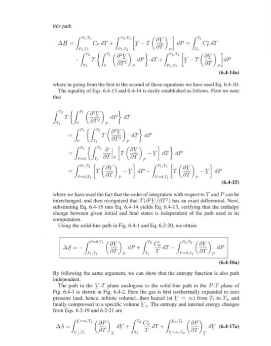
The Evaluation of H,U, and S To compute the change in enthalpy in going from the state (T1,P1) to the state (T2,P2), we start from H=H(T2,P2)H(T1,P1)=T1,P1T2,P2dH and note that since enthalpy is a state function, we can compute its change between two states by evaluating the integral along any convenient path. In particular, if the path indicated by the solid line in Fig. 6.4-1 is used (isothermal expansion followed by isobaric heating and isothermal compression), we have, from Eq. 6.2-22, H=P1,T1P=0,T1[VT(TV)P]dP+T1,P=0T2,P=0CPdT+P=0,T2P2,T2[VT(TV)P]dP Alternatively, we could compute the enthalpy change using the path indicated by the dashed line in Fig. 6.4-1-isobaric heating followed by isothermal compression. For Figure 6.4-1 Two paths for the integration of Eq. 6.4-12. this path H=R1,T1P1,T2CPdT+R1,T2P2,T2[VT(TV)P]dP=T1T2CPdTT1T2T{0P1(T22V)PdP}dT+P2,T2P2,T2[VT(TV)P]dP where in going from the first to the second of these equations we have used Eq. 6.4-10. The equality of Eqs. 6.4-13 and 6.4-14 is easily established as follows. First we note that T1T2T{0P1(T22V)PdP}dT=0R1{T1T2T(T22V)PdT}dP=P=0P1{T1T2TP[T(TV)PV]P}dP=P=0T2P1x2[T(TV)PV]dPP=0x2P1T1[T(TV)PV]dP where we have used the fact that the order of integration with respect to T and P can be interchanged, and then recognized that T(2V/T2) has an exact differential. Next, substituting Eq. 6.4-15 into Eq. 6.4-14 yields Eq. 6.4-13, verifying that the enthalpy change between given initial and final states is independent of the path used in its computation. Using the solid-line path in Fig. 6.4-1 and Eq. 6.2-20, we obtain S=P1,T1P=0,T1(TV)PdP+T1T2TCpdTP=0,T2P2,T2(TV)PdP (6.416a) By following the same argument, we can show that the entropy function is also path independent. The path in the VT plane analogous to the solid-line path in the PT plane of Fig. 6.4-1 is shown in Fig. 6.4-2. Here the gas is first isothermally expunded to zero pressure (and, hence, infinite volume), then heated (at V= ) from T1 to T2, and finally compressed to a specific volume V2. The entropy and internal energy changes from Eqs. 6.2-19 and 6.2-21 are Figure 6.4-2 Integration path in the VT plane. and U=Y1,T1YT1[T(TP)YP]dV+T1T2CVdT+V=,T2Y2,T2[T(TP)YP]dV It can be easily shown that alternative paths lead to identical results for S and U. Note that only Cp,CV, and terms related to the volumetric equation of state appear in Eqs. 6.4-13, 6.4-14a, 6.4-16a, 6.4-17a, and 6.4-18. Thus, as has already been pointed out, we do not need heat capacity data at all densities, but merely in the low-density (ideal gas) limit and volumetric equation-of-state information. Given Cp or CV data and volumetric equation-of-state data (in either analytic or tabular form), it is possible to compute H,U, and S for any two states of a fluid: given the value of S in any one state, it is also possible to compute G and A. Thus. we now have the equations necessary to construct complete tables or charts interrelating H.U.S,T,P, and V, such as those in Chapter 3. Although the process of constructing thermodynamic properties tables and charts is tedious (see Mllustration 6.4-1), their availability, as we saw in Chapters 3,4 and 5, makes it possible to use the balance equations to solve thermodynamic problems for real fluids quickly and with good accuracy. It is interesting to compare the equations just derived with the analogous results for an ideal gas. Since (TV)P1G=(TV)P1G=TV=PRsoV1GT(TV)P1G=0 and (TP)Y1C=VR=TP we have HiG(T2,P2)H1G(T1,P1)=T1,P=0T2,P=0CppdT =T1T2TCvdT+RlnV1V2 Thus, comparing Eqs. 6.4-14a and b, Eqs. 6.4-17a and b, and Eqs. 6.4-16a and b, we have for the real fluid H(T2,P2)H(T1,P1)=HK(T2,P2)HBC(T1,P1)+T1,R1T1,P=0[VT(TV)P]dP+T2,P=0T2,R2[VT(TV)P]dP=HIG(T2,P2)H1C(T1,P1)+(HH1CG)r2,P2(HH1C)T1,n and S(T2,V2)S(T1,V1)=SIG(T2,V2)S4G(T1,V1)+T1Y1T1Y1=x[(TP)YVR]dV+T2,Y2=xT2Y2[(TP)YVR]dV=SiG(T2,V2)SAC(T1,V1)+(SSiC)n2,V2(SSiC)n1Y1 where (HHIG)T,P=T,P=0T,P[VT(TV)P]dP (SS1G)T,P=T,P=0T,P[(TV)PPR]dP and (SS1G)T,Y=S(T,V)SIG(T,V)=T,V=TY[(TP)YVR]dV The interpretation of Eqs. 6.4-19,6.4-20, and 6.4-21 is clear: The changes in enthalpy and entropy of a real fluid are equal to those for an ideal gas undergoing the same change of state plus the departure of the fluid from ideal gas behavior at the end state less the departure from ideal gas behavior of the initial state. These departure functions, given by Eqs. 6.422,6.423, and 6.424, can be computed once the fluid equation of state is known. Before leaving this subject, we note that although Eqs. 6.4-22, 6.4-23, and 6.4-24 are useful for calculating the enthalpy and entropy departures from ideal gas behavior for some equations of state, their form is less helpful for the van der Waals, PengRobinson and other equations of state considered in this section in which V and T are the convenient independent variables. 12 In such cases it is useful to have alternative expressions for the departure functions at fixed temperature and pressure. To obtain such expressions, we start with Eqs. 6.4-22 and 6.423 and use dP=V1d(PV)VPdV and the triple product rule (Eq. 6.1-6a) in the form (TV)P(VP)T(PT)V=1or(TV)PdPT=(TP)YdVT to obtain P=0P[VT(TV)P]dP==PV=RTPY(T,P)d(PV)+V=V=V(T,P)[T(TP)YP]dV(PVRT)+Y=VV(T,P)[T(TP)YP]dV therefore H(T,P)HIG(T,P)=RT(Z1)+Y=Y=Y(T,P)[T(TP)YP]dV As an introduction to the problem of constructing a chart or table of the thermodynamic properties of a real fluid, develop a thermodynamic properties chart for oxygen over the temperature range of 100C to +150C and a pressure range of 1 to 100 bar. (A larger temperature range, including the vapor-liquid two-phase region, will be considered in Chapter 7.) In particular, calculate the compressibility factor, specific volume, molar enthalpy, and molar entropy as a function of temperature and pressure. Also, prepare a pressure-volume plot, a pressure-enthalpy plot (see Fig. 3.4-2), and a temperature-entropy plot (see Fig. 3.4-3) for oxygen. Data: For simplicity we will assume oxygen obeys the Peng-Robinson equation of state and has an ideal gas heat capacity given by CP(molKJ)=25.46+1.519102T0.7151105T2+1.311109T3 We will choose the reference state of oxygen to be the ideal gas state at 25C and 1 bar: HIG(T=25C,P=1bar)=0 and S1G(T=25C,P=1bar)=0 As will be explained shortly, the Peng-Robinson parameters for oxygen are a(T)b(T)[(T)]1/2=0.45724PcR2Tc2(T)=0.07780PcRTc=1+(1TcT) where =0.4069,Tc=154.6K is the critical temperature of oxygen, and P=5.046MPa is its critical pressure. 1. Volume The volume is the easiest of the properties to calculate. For each value of temperature we compute values for a(T) and b, and then at each pressure solve the equation P=VbRTV(V+b)+b(Vb)a(T) for the volume, or equivalently (and preferably), solve the equation Z3+(1+B)Z2+(A3B22B)Z+(AB+B2+B3)=0 with B=bP/RT and A=aP/(RT)2 (see Eq. 6.4-4 and Table 6.4-3) for the compressibility factor Z=PV/RT, from which the volume is easily calculated as V=ZRT/P. Repeat- 'Igure 6.4-5 rressure-volume dagram tor oxygen canculated usang the reng-koonson equation of state. 11. Enthalpy To compute the difference in the enthalpy of oxygen between a state of temperature T and pressure P and the ideal gas reference state at 25C and I bar, we use =(HH16)T,F+25.46(T296.15)+21.519102(T2298.152)30.7151105(T3298.153)+41.311109(T4298.154) The quantity (HH10)r,is is computed using Eq. 6.4-29 and the value of the compressibilify factor Z found earlier at each set of (T,P) values. The values of enthalpy computed in this manner appear in Table 6.4.4 and have been ploted in Fig. 6.4-4 as a pressure and enthalpy diagram. The Peng-Robinson program (Appendices B.I-3 and B.II-1) was used for this calculation as well. (Note that it T=25C and P=1 bar, oxygen is not quite an ideal gas; Z=0.9991, not unity. Consequently, (HH1C)T=2sC,P=1kar=9,44J/mol, so that the enthalpy of oxygen at T=25C,P=1 bar is 9.44J/mol, whereas if it were an ideal gas at these conditions its enthalpy would be zero.] Once again, lower-lemperature results, including the two-phase region. appear in Fig 6.4-6. The basis for those calculations will be discussed in Sec. 7.5


