Answered step by step
Verified Expert Solution
Question
1 Approved Answer
EXAMPLE 4.15 A geared turbofan (GTF) is used in a UHB engine with a single-stage, low-pressure ratio fan. The engine design point is at

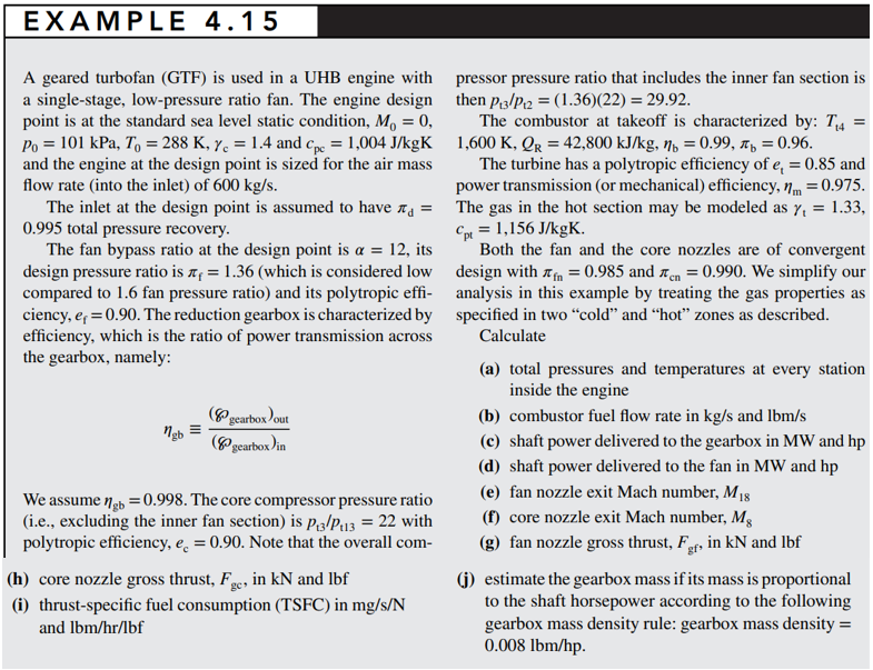
EXAMPLE 4.15 A geared turbofan (GTF) is used in a UHB engine with a single-stage, low-pressure ratio fan. The engine design point is at the standard sea level static condition, Mo = 0, Po = 101 kPa, To = 288 K, y = 1.4 and C = 1,004 J/kgK and the engine at the design point is sized for the air mass flow rate (into the inlet) of 600 kg/s. pressor pressure ratio that includes the inner fan section is then P3/P = (1.36)(22) = 29.92. The combustor at takeoff is characterized by: T4 = 1,600 K, QR = 42,800 kJ/kg, = 0.99, = 0.96. The turbine has a polytropic efficiency of e = 0.85 and power transmission (or mechanical) efficiency, m = 0.975. The inlet at the design point is assumed to have = The gas in the hot section may be modeled as y = 1.33, 0.995 total pressure recovery. The fan bypass ratio at the design point is a = 12, its design pressure ratio is = 1.36 (which is considered low compared to 1.6 fan pressure ratio) and its polytropic effi- ciency, eq = 0.90. The reduction gearbox is characterized by efficiency, which is the ratio of power transmission across the gearbox, namely: ngb = (gearbox) out (gearbox) in We assume gb = 0.998. The core compressor pressure ratio (i.e., excluding the inner fan section) is p3/P113 = 22 with polytropic efficiency, e = 0.90. Note that the overall com- (h) core nozzle gross thrust, F., in kN and lbf (i) thrust-specific fuel consumption (TSFC) in mg/s/N and lbm/hr/lbf Cpt = 1,156 J/kgK. Both the fan and the core nozzles are of convergent design with = 0.985 and n = 0.990. We simplify our analysis in this example by treating the gas properties as specified in two "cold" and "hot" zones as described. Calculate (a) total pressures and temperatures at every station inside the engine (b) combustor fuel flow rate in kg/s and lbm/s (c) shaft power delivered to the gearbox in MW and hp (d) shaft power delivered to the fan in MW and hp (e) fan nozzle exit Mach number, M18 (f) core nozzle exit Mach number, Mg (g) fan nozzle gross thrust, For, in kN and lbf gf (j) estimate the gearbox mass if its mass is proportional to the shaft horsepower according to the following gearbox mass density rule: gearbox mass density = 0.008 lbm/hp.
Step by Step Solution
There are 3 Steps involved in it
Step: 1

Get Instant Access to Expert-Tailored Solutions
See step-by-step solutions with expert insights and AI powered tools for academic success
Step: 2

Step: 3

Ace Your Homework with AI
Get the answers you need in no time with our AI-driven, step-by-step assistance
Get Started


