Answered step by step
Verified Expert Solution
Question
1 Approved Answer
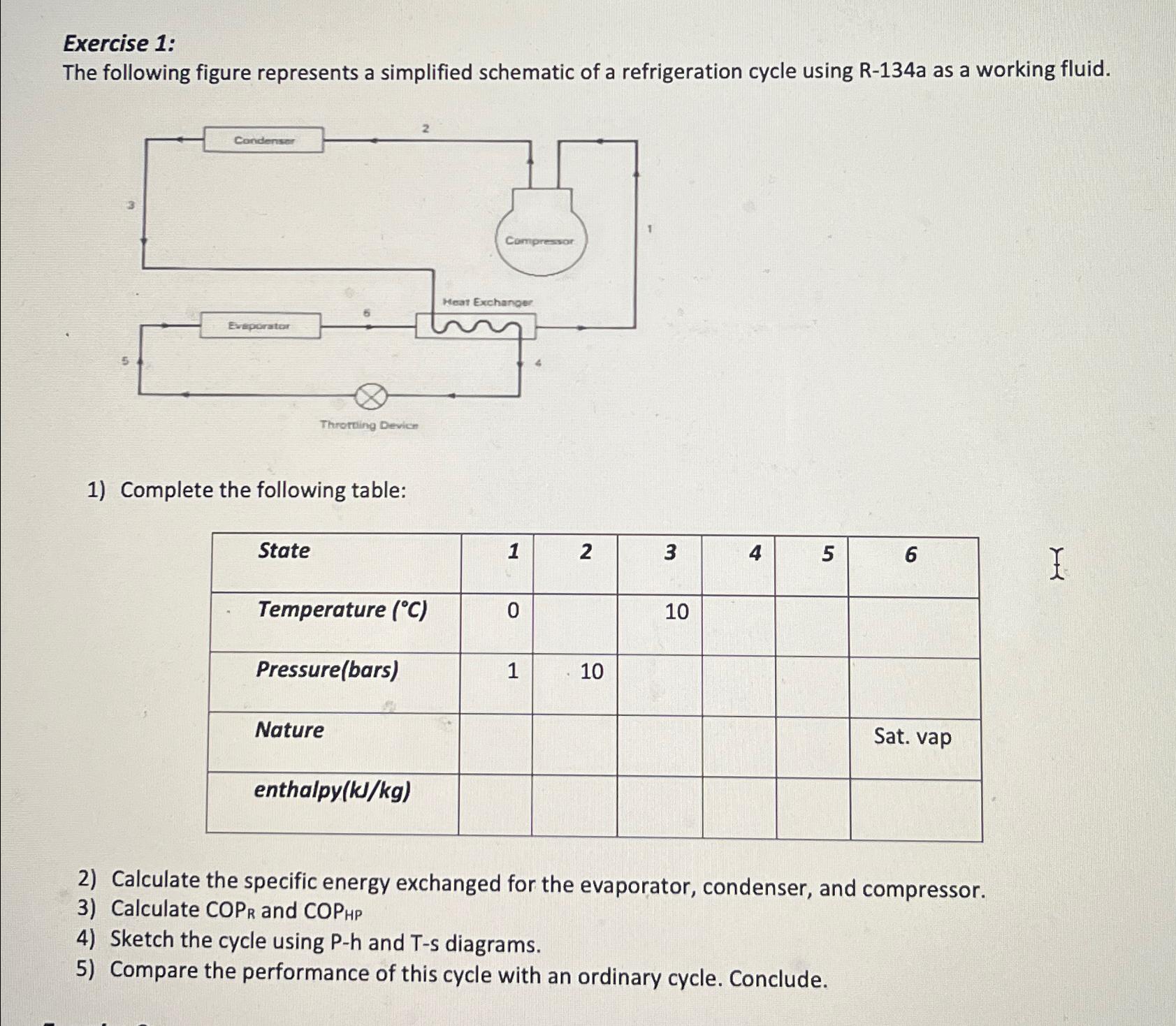
Exercise 1: The following figure represents a simplified schematic of a refrigeration cycle using R-134a as a working fluid. Condenser Compressor Heat Exchanger Evaporator

Exercise 1: The following figure represents a simplified schematic of a refrigeration cycle using R-134a as a working fluid. Condenser Compressor Heat Exchanger Evaporator Throttling Device 1) Complete the following table: State Temperature (C) Pressure(bars) Nature enthalpy(kJ/kg) 1 2 3 4 5 6 I 0 1 10 10 Sat. vap 2) Calculate the specific energy exchanged for the evaporator, condenser, and compressor. 3) Calculate COPR and COPHP 4) Sketch the cycle using P-h and T-s diagrams. 5) Compare the performance of this cycle with an ordinary cycle. Conclude.
Step by Step Solution
There are 3 Steps involved in it
Step: 1

Get Instant Access to Expert-Tailored Solutions
See step-by-step solutions with expert insights and AI powered tools for academic success
Step: 2

Step: 3

Ace Your Homework with AI
Get the answers you need in no time with our AI-driven, step-by-step assistance
Get Started


