Answered step by step
Verified Expert Solution
Question
1 Approved Answer
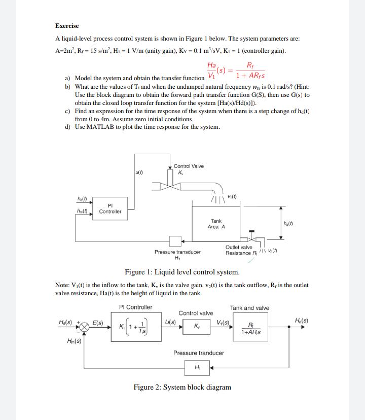
Exercise A liquid-level process control system is shown in Figure 1 below. The system parameters are: A=2m, RF = 15 s/m, H = 1

Exercise A liquid-level process control system is shown in Figure 1 below. The system parameters are: A=2m, RF = 15 s/m, H = 1 V/m (unity gain), Kv=0.1 m/sV, K = 1 (controller gain). Rf 1+ ARfs a) Model the system and obtain the transfer function b) What are the values of T, and when the undamped natural frequency wn is 0.1 rad/s? (Hint: Use the block diagram to obtain the forward path transfer function G(S), then use G(s) to obtain the closed loop transfer function for the system [Ha(s)/Hd(s)]). c) Find an expression for the time response of the system when there is a step change of ha(t) from 0 to 4m. Assume zero initial conditions. d) Use MATLAB to plot the time response for the system. h0 he(0) He(s) PI Controller H_(s) E(s) LI(1) Control Valve K Pressure transducer H Ha -(s) U(s) /HIN Tank Area A Figure 1: Liquid level control system. Note: V(t) is the inflow to the tank, K, is the valve gain, v(t) is the tank outflow, R, is the outlet valve resistance, Ha(t) is the height of liquid in the tank. PI Controller H Control valve K VI(1) Pressure tranducer Outlet valve Resistance R V(s) /1\ V (1) Tank and valve Figure 2: System block diagram h(1) R 1+ARS H(s)
Step by Step Solution
There are 3 Steps involved in it
Step: 1
A 2 Ry 15 H 1 Ku01 R 1 Equation between PI Controller and Centrod value 4 kilit s hd Ti ...
Get Instant Access to Expert-Tailored Solutions
See step-by-step solutions with expert insights and AI powered tools for academic success
Step: 2

Step: 3

Ace Your Homework with AI
Get the answers you need in no time with our AI-driven, step-by-step assistance
Get Started


