Answered step by step
Verified Expert Solution
Question
1 Approved Answer
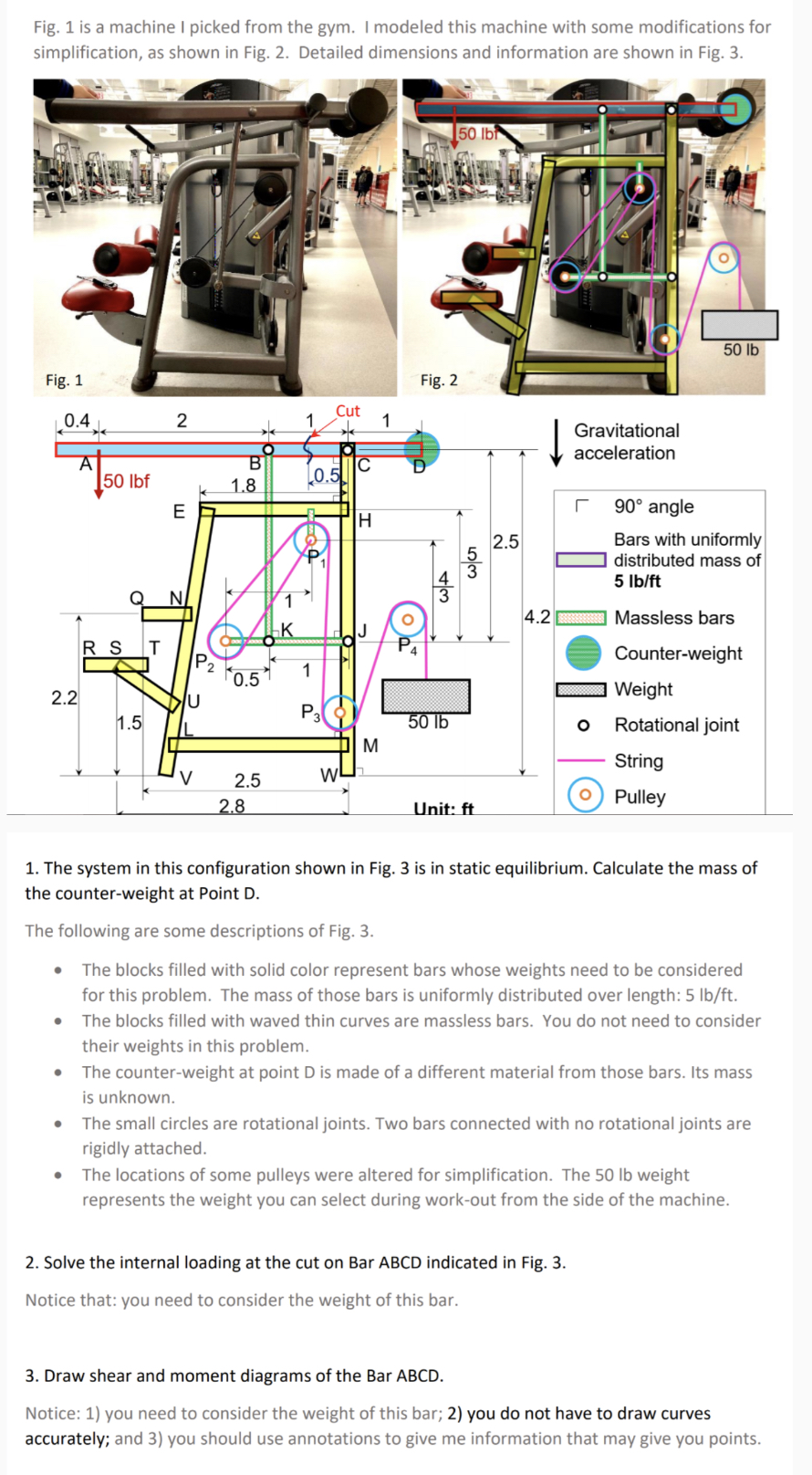
Fig. 1 is a machine I picked from the gym. I modeled this machine with some modifications for simplification, as shown in Fig. 2.

Fig. 1 is a machine I picked from the gym. I modeled this machine with some modifications for simplification, as shown in Fig. 2. Detailed dimensions and information are shown in Fig. 3. 50 lb Fig. 1 Fig. 2 Cut 0.4 2 1 1 A B C 50 lbf 0.5 k 1.8 E H 43 50 lb Gravitational acceleration 2.5 90 angle Bars with uniformly distributed mass of 5 lb/ft 4.2 Massless bars Counter-weight 53 RS P 0.5 Weight 2.2 U P3 1.5 50 lb Rotational joint IL M String V W 2.5 Pulley 2.8 Unit: ft 1. The system in this configuration shown in Fig. 3 is in static equilibrium. Calculate the mass of the counter-weight at Point D. The following are some descriptions of Fig. 3. The blocks filled with solid color represent bars whose weights need to be considered for this problem. The mass of those bars is uniformly distributed over length: 5 lb/ft. The blocks filled with waved thin curves are massless bars. You do not need to consider their weights in this problem. The counter-weight at point D is made of a different material from those bars. Its mass is unknown. The small circles are rotational joints. Two bars connected with no rotational joints are rigidly attached. The locations of some pulleys were altered for simplification. The 50 lb weight represents the weight you can select during work-out from the side of the machine. 2. Solve the internal loading at the cut on Bar ABCD indicated in Fig. 3. Notice that: you need to consider the weight of this bar. 3. Draw shear and moment diagrams of the Bar ABCD. Notice: 1) you need to consider the weight of this bar; 2) you do not have to draw curves accurately; and 3) you should use annotations to give me information that may give you points.
Step by Step Solution
There are 3 Steps involved in it
Step: 1

Get Instant Access to Expert-Tailored Solutions
See step-by-step solutions with expert insights and AI powered tools for academic success
Step: 2

Step: 3

Ace Your Homework with AI
Get the answers you need in no time with our AI-driven, step-by-step assistance
Get Started


