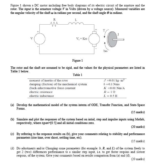
Figure 1 shown a DC motor including free body diagrams of its electric circuit of the amature and the rotor. The input is the
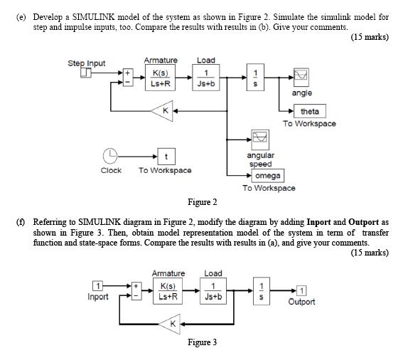
Figure 1 shown a DC motor including free body diagrams of its electric circuit of the amature and the rotor. The input is the amature voltage V in Volts (driven by a voltage source). Measured variables are the angular velocity of the shaft w in radians per second, and the shaft angle e in radians. R V, - Ko be Figure 1 The rotor and the shaft are assumed to be rigid, and the values for the physical parameters are listed in Table 1 below. Table 1 moment of inertia of the rotor damping (friction) of the mechanical system J=0.01 kg m b =0.1 Nms K =0.01 Nm/A (back-)electromotive force constant electric resistance R=12 electric inductance L =0.5 H (a) Develop the mathematical model of the system intem of ODE, Transfer Function, and State-Space Forms. (15 marks) (b) Simulate and plot the responses of the system based on intial, step and impulse inputs using Matlab, respectively, where tspan=[0 5] and all initial conditions zero. (20 marks) (c) By refering to the response results on (b), give your comments relating to stability and performance parameters (rise time, over shoot, settling time, etc). (15 marks) (d) Do adustments and/or Changing some parameters (for example: b, R, and L) of the system freely to get 2 (two) differences performance to a similar step input, i.e. to get faster respons and slower respons, of the system. Give your comments based on results comparison from (a) and (d). (20 marks) (e) Develop a SIMULINK model of the system as shown in Figure 2. Simulate the simulink model for step and impulse inputs, too. Compare the results with results in (b). Give your comments. (15 marks) Step Input Armature Load K(S) Ls+R Js+b angle K theta To Workspace angular speed Clock To Workspace omega To Workspace Figure 2 ( Referring to SIMULINK diagram in Figure 2, modify the diagram by adding Inport and Outport as shown in Figure 3. Then, obtain model representation model of the system in term of transfer function and state-space forms. Compare the results with results in (a), and give your comments. (15 marks) Armature Load K(s) Ls+R Inport Js+b Outport K Figure 3
Step by Step Solution
3.46 Rating (172 Votes )
There are 3 Steps involved in it
Step: 1
b matlab clc clear all close all stfs j001 b01 k001 r1 l05 gklsrjsbk2 motor transfer function st...
See step-by-step solutions with expert insights and AI powered tools for academic success
Step: 2

Step: 3

Ace Your Homework with AI
Get the answers you need in no time with our AI-driven, step-by-step assistance
Get Started


