Answered step by step
Verified Expert Solution
Question
1 Approved Answer
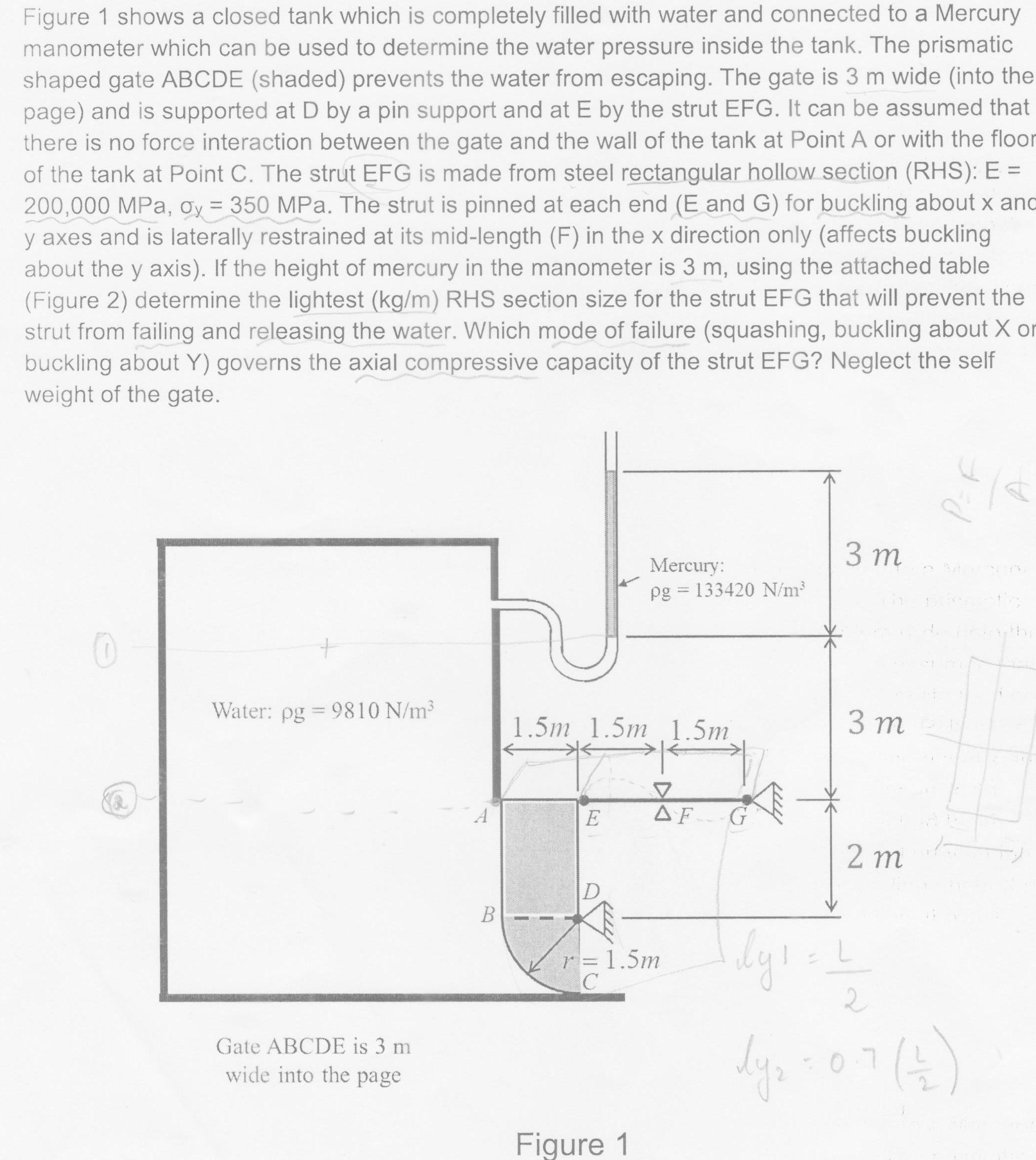
Figure 1 shows a closed tank which is completely filled with water and connected to a Mercury manometer which can be used to determine


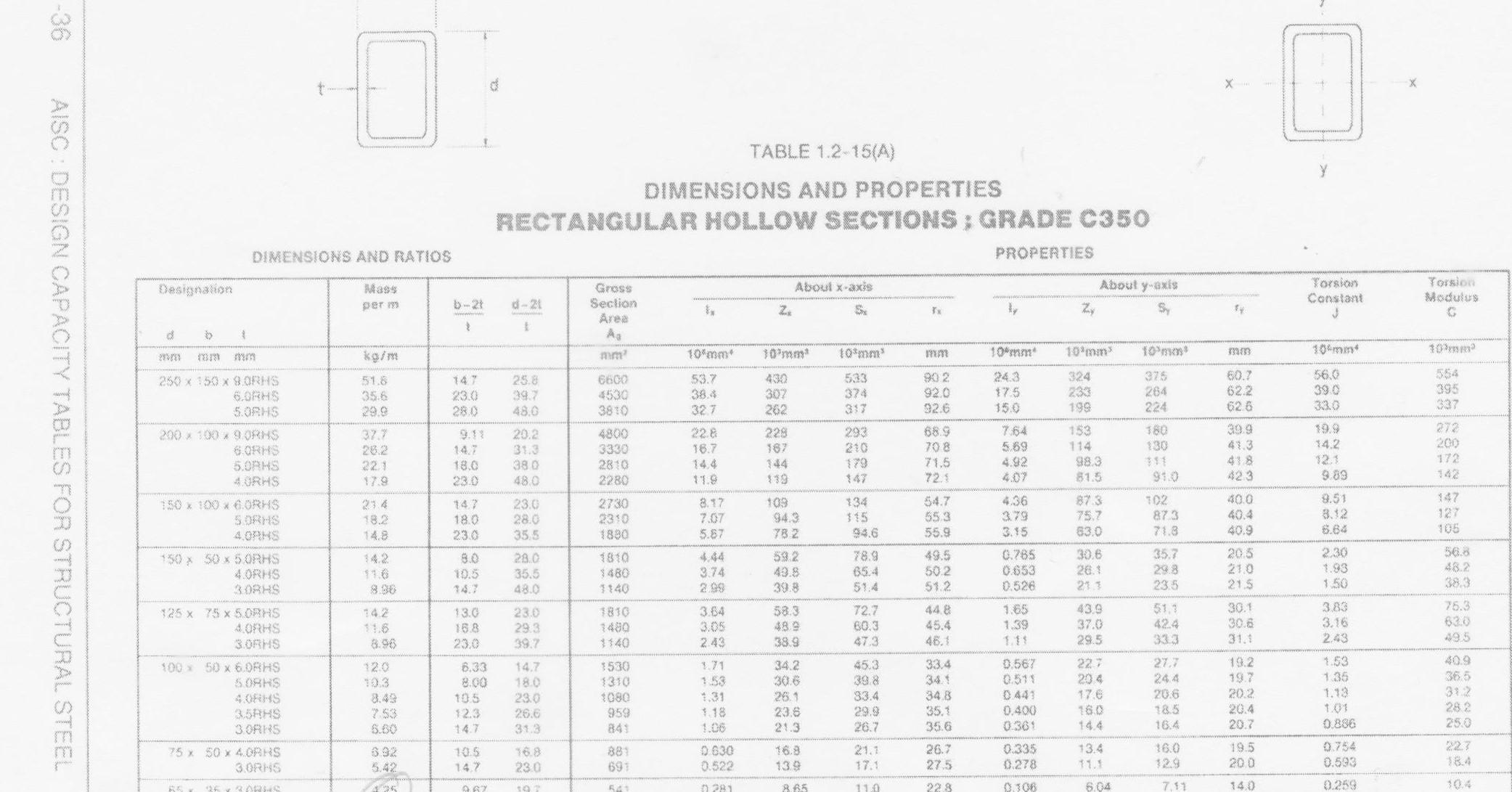
Figure 1 shows a closed tank which is completely filled with water and connected to a Mercury manometer which can be used to determine the water pressure inside the tank. The prismatic shaped gate ABCDE (shaded) prevents the water from escaping. The gate is 3 m wide (into the page) and is supported at D by a pin support and at E by the strut EFG. It can be assumed that there is no force interaction between the gate and the wall of the tank at Point A or with the floor of the tank at Point C. The strut EFG is made from steel rectangular hollow section (RHS): E 200,000 MPa, oy = 350 MPa. The strut is pinned at each end (E and G) for buckling about x anc y axes and is laterally restrained at its mid-length (F) in the x direction only (affects buckling about the y axis). If the height of mercury in the manometer is 3 m, using the attached table (Figure 2) determine the lightest (kg/m) RHS section size for the strut EFG that will prevent the strut from failing and releasing the water. Which mode of failure (squashing, buckling about X or buckling about Y) governs the axial compressive capacity of the strut EFG? Neglect the self weight of the gate. 3 m Mercury: pg = 133420 N/m Water: pg = 9810 N/m3 3 m 1.5m 1.5m 1.5m AF 2 m r= 1.5m 07( Gate ABCDE is 3 m wide into the page Figure 1 TABLE 1.2-15(A) DIMENSIONS AND PROPERTIES SECTIONS; GRADE C350 RECTANGULAR HOLLOW PROPERTIES DIMENSIONS AND RATIOS Torsion Modulus Torsion Constant About y-axis About x-axis Gross Seclion Area Mass Designation d-21 b-2t per m S. Ag 10Pmm 10'mxn 10 mm 10 mm* 10'mm 10*mm 10 mm 10 mm kg/m 554 395 337 60.7 62.2 62.6 56.0 39.0 33.0 324 233 199 375 264 224 90 2 92.0 92.6 24.3 53.7 38.4 327 430 307 262 6600 4530 3810 533 374 317 250 x 150 x 8.0RHS 6.ORHS 5.0RHS 51.8 35.6 29.9 147 25.8 39.7 48.0 17.5 23.0 15.0 28.0 272 200 172 142 7.64 569 4.92 4.07 39.9 43.3 418 42.3 19.9 153 180 130 11 91.0 228 68.9 22.8 16.7 14.4 293 200 x 100 9.0RHS 6 ORMS 5.0RHS 4.ORHS 20.2 31.3 4800 3330 2810 2280 37.7 26.2 22.1 9.11 14.2 12.1 9.89 114 98.3 81.5 70 8 71.5 72.1 210 179 147 167 144 119 14.7 18.0 38 0 48.0 11.9 17.9 23.0 147 127 105 9.51 8.12 6.64 102 87.3 71.8 40.0 40.4 40.9 54.7 4.36 3.79 87.3 75.7 63.0 109 94.3 8.17 7.07 5.87 134 $15 94.6 150 x 100 x 6.ORHS 5.0RHS 14.7 18.0 23.0 23.0 28.0 35.5 2730 2310 1880 214 18.2 55.3 55.9 3.15 78 2 4.0RHS 14.8 56.8 48.2 38.3 2.30 20.5 21.0 21.5 30.6 26.1 21.3 35.7 29.8 0.765 0.653 0.526 49.5 50.2 51.2 4.44 3.74 2 99 59.2 78.9 150 x 50 x 5 ORHS 4.0RHS 3.08HS 28.0 35.5 48.0 1810 14.2 11.6 8.96 8.0 1.93 65.4 43.8 1480 10.5 1.50 23.5 39.8 51.4 40 14.7 75.3 63.0 49.5 3.83 30.1 30.6 31.1 51.1 42.4 33.3 1.65 1.39 1.11 43.9 37.0 29.5 44.8 45.4 3.64 3.05 2.43 58.3 48.9 38.9 72.7 60.3 142 11.6 8.96 23.0 29.3 39.7 1810 1480 1140 125 x 75 x 5.0RHS 4.ORHS 3.ORHS 13.0 16.8 3.16 2.43 46.1 47.3 23.0 1.53 1.35 1.13 1.01 0.886 40.9 36.5 312 28.2 19.2 19.7 20.2 227 20 4 27.7 24.4 20.6 185 45.3 39.8 0.567 0.511 34.2 30.6 33.4 34.1 34.8 35.1 35.6 100 x 50 x 6.0RHS SORKS 1.71 6.33 8.00 10.5 1530 1310 1080 12.0 14.7 18.0 23.0 26.6 31.3 1.53 10.3 0.441 0.400 0.361 17.6 33.4 29.9 26.7 1,31 1.18 1.06 26.1 23.6 21.3 4.OFHS 35RHS 3.0RHS 8.49 753 5.60 20.4 20.7 16.0 959 841 12.3 14.7 25.0 16.4 14.4 22.7 0.754 O 630 16.0 12.9 19.5 200 26.7 27.5 0.335 0.278 13.4 21.1 16.8 75 x 50 x 4.ORHS 881 392 10.5 14.7 16.8 18.4 0.593 11.1 13.9 17.1 0.522 23.0 691 5.42 3.0RHS 10.4 0.259 14.0 0.106 7,11 228 6.04 110 -36 AISC : DESIGN CAPACITY TABLES FOR STRUCTURAL STEEL
Step by Step Solution
There are 3 Steps involved in it
Step: 1

Get Instant Access to Expert-Tailored Solutions
See step-by-step solutions with expert insights and AI powered tools for academic success
Step: 2

Step: 3

Ace Your Homework with AI
Get the answers you need in no time with our AI-driven, step-by-step assistance
Get Started


