Answered step by step
Verified Expert Solution
Question
1 Approved Answer
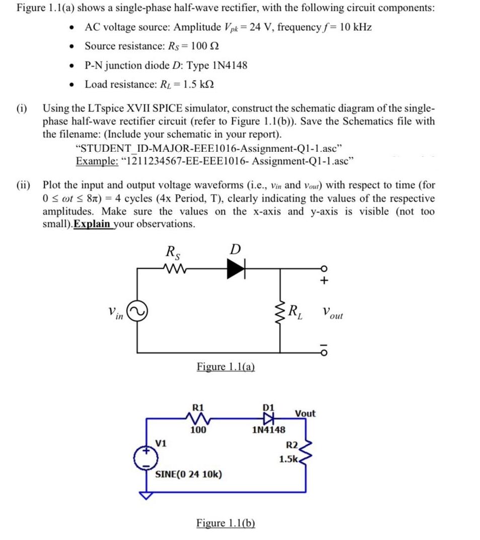
Figure 1.1(a) shows a single-phase half-wave rectifier, with the following circuit components: AC voltage source: Amplitude Vpk = 24 V, frequency f= 10 kHz

Figure 1.1(a) shows a single-phase half-wave rectifier, with the following circuit components: AC voltage source: Amplitude Vpk = 24 V, frequency f= 10 kHz Source resistance: Rs 100 2 P-N junction diode D: Type 1N4148 Load resistance: R = 1.5 k (i) Using the LTspice XVII SPICE simulator, construct the schematic diagram of the single- phase half-wave rectifier circuit (refer to Figure 1.1(b)). Save the Schematics file with the filename: (Include your schematic in your report). "STUDENT_ID-MAJOR-EEE1016-Assignment-Q1-1.asc" Example: "1211234567-EE-EEE1016- Assignment-Q1-1.asc" (ii) Plot the input and output voltage waveforms (i.e., Vin and vout) with respect to time (for 0 t 8n) = 4 cycles (4x Period, T), clearly indicating the values of the respective amplitudes. Make sure the values on the x-axis and y-axis is visible (not too small). Explain your observations. Rs www V1 Figure 1.1(a) R1 100 D SINE(0 24 10k) D1 1N4148 Figure 1.1(b) R Vout R2 1.5k + V out
Step by Step Solution
★★★★★
3.55 Rating (152 Votes )
There are 3 Steps involved in it
Step: 1
Analysis of SinglePhase HalfWave Rectifier Circuit This document addresses the analysis of a singlephase halfwave rectifier circuit using LTspice XVII SPICE simulator as depicted in Figure 11a 1 The c...
Get Instant Access to Expert-Tailored Solutions
See step-by-step solutions with expert insights and AI powered tools for academic success
Step: 2

Step: 3

Ace Your Homework with AI
Get the answers you need in no time with our AI-driven, step-by-step assistance
Get Started


