Question
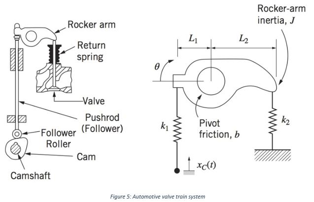
Figure 5 shows a schematic of an automotive valve train. The rotating cam moves the pushrod (follower), and the rocker-arm rotates to move the valve
Figure 5 shows a schematic of an automotive valve train. The rotating cam moves the pushrod (follower), and the rocker-arm rotates to move the valve in the vertical direction. A simplified mechanical model is shown adjacent to the valve train schematic diagram. Moment of inertia J represents the rocker-arm inertia about the pivot point. Deflection of the pushrod is modeled by spring k1 and the return spring on the valve is k2.Friction in the rocker arm pivot is modeled by viscous damping coefficient b. The vertical motion of the cam follower is xc(t), the input to the system. Angular position of the rocker arm is q, which is positive in the clockwise directional. When the rocker-arm angle is level (q = 0), the return spring has a compressive preload force of FL. When cam follower position xc = 0 and q = 0, then the pushrod(k1) is undeflected. Assume that rocker-arm angle q remains small at all times. Derive the mathematical model of the valve train system and determine the required displacement of the cam follower xc when the system is at rest (equilibrium)with a level rocker arm (q = 0).
AMA www. Rocker arm Camshaft Return spring Follower Roller -Valve Pushrod (Follower) Cam 0 k L Pivot friction, b xc(t) 12 Figure 5: Automotive valve train system Rocker-arm inertia, J k
Step by Step Solution
3.50 Rating (157 Votes )
There are 3 Steps involved in it
Step: 1
The mathematical model of the valve train system can be derived by considering the forces acting on ...
Get Instant Access to Expert-Tailored Solutions
See step-by-step solutions with expert insights and AI powered tools for academic success
Step: 2

Step: 3

Ace Your Homework with AI
Get the answers you need in no time with our AI-driven, step-by-step assistance
Get Started


