Answered step by step
Verified Expert Solution
Question
1 Approved Answer
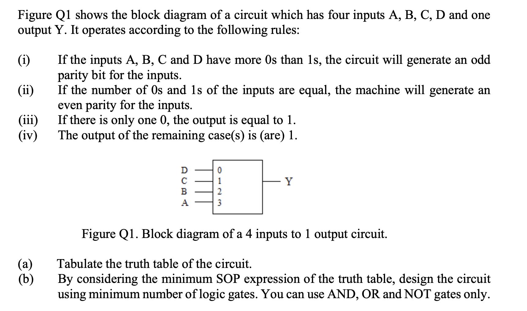
Figure Q1 shows the block diagram of a circuit which has four inputs A, B, C, D and one output Y. It operates according

Figure Q1 shows the block diagram of a circuit which has four inputs A, B, C, D and one output Y. It operates according to the following rules: (i) (ii) (iii) (iv) (a) (b) If the inputs A, B, C and D have more Os than 1s, the circuit will generate an odd parity bit for the inputs. If the number of Os and 1s of the inputs are equal, the machine will generate an even parity for the inputs. If there is only one 0, the output is equal to 1. The output of the remaining case(s) is (are) 1. DUBA Y Figure Q1. Block diagram of a 4 inputs to 1 output circuit. Tabulate the truth table of the circuit. By considering the minimum SOP expression of the truth table, design the circuit using minimum number of logic gates. You can use AND, OR and NOT gates only.
Step by Step Solution
★★★★★
3.39 Rating (158 Votes )
There are 3 Steps involved in it
Step: 1
a Truth Table A 0 O 0 O 0 O 0 1 1 1 1 1 1 1 1 B Circuit Design O O O O 1 1 1 1 O O O O ...
Get Instant Access to Expert-Tailored Solutions
See step-by-step solutions with expert insights and AI powered tools for academic success
Step: 2

Step: 3

Ace Your Homework with AI
Get the answers you need in no time with our AI-driven, step-by-step assistance
Get Started


