Question
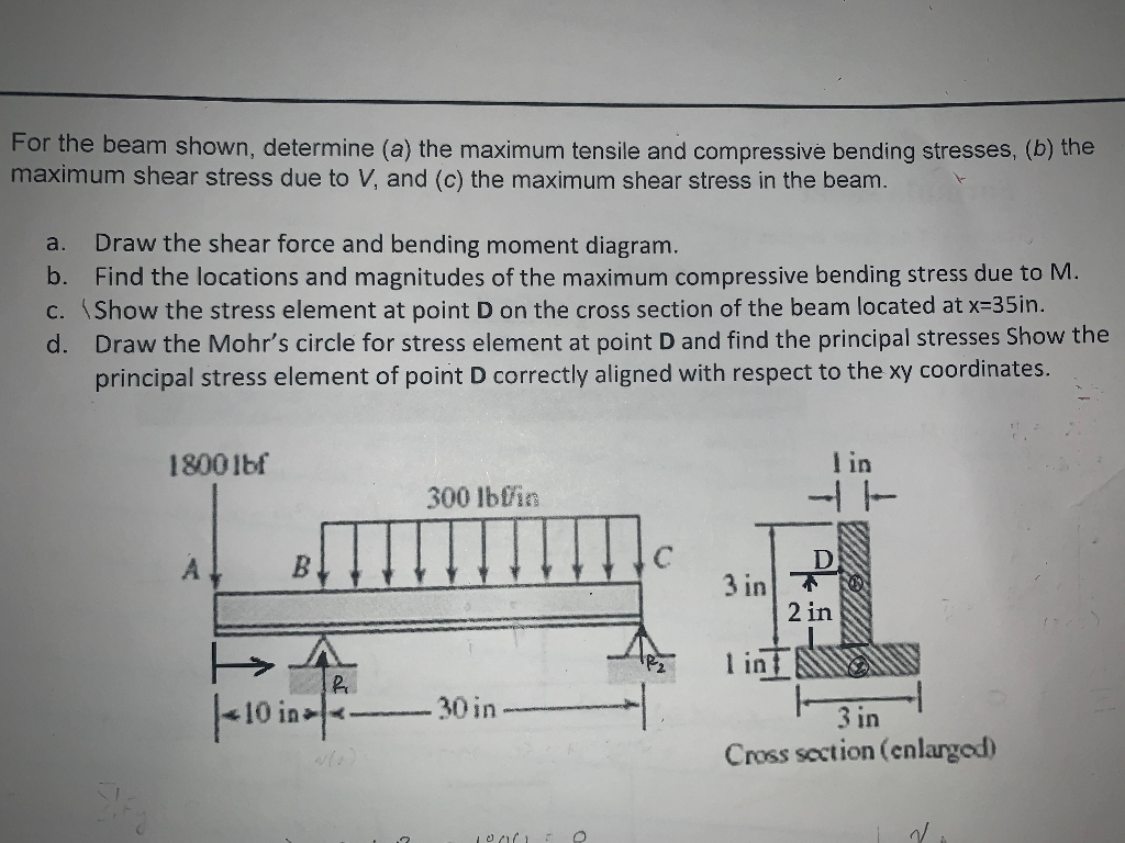
For the beam shown, determine (a) the maximum tensile and compressive bending stresses, (b) the maximum shear stress due to V, and (c) the

For the beam shown, determine (a) the maximum tensile and compressive bending stresses, (b) the maximum shear stress due to V, and (c) the maximum shear stress in the beam. a. Draw the shear force and bending moment diagram. b. Find the locations and magnitudes of the maximum compressive bending stress due to M. c. Show the stress element at point D on the cross section of the beam located at x=35in. d. Draw the Mohr's circle for stress element at point D and find the principal stresses Show the principal stress element of point D correctly aligned with respect to the xy coordinates. Stea 1800lbf AL B fr 10 in- 300 lbfin -30 in- 1000: O I in 41 D 3 in F 2 in lint 3 in Cross section (enlarged) N.
Step by Step Solution
3.37 Rating (147 Votes )
There are 3 Steps involved in it
Step: 1

Get Instant Access to Expert-Tailored Solutions
See step-by-step solutions with expert insights and AI powered tools for academic success
Step: 2

Step: 3

Ace Your Homework with AI
Get the answers you need in no time with our AI-driven, step-by-step assistance
Get StartedRecommended Textbook for
Shigleys Mechanical Engineering Design
Authors: Richard G. Budynas, J. Keith Nisbett
9th edition
77679520, 73529281, 1259986241, 978-0077679521, 9780073529288, 9781259986246, 978-1121345317
Students also viewed these Mechanical Engineering questions
Question
Answered: 1 week ago
Question
Answered: 1 week ago
Question
Answered: 1 week ago
Question
Answered: 1 week ago
Question
Answered: 1 week ago
Question
Answered: 1 week ago
Question
Answered: 1 week ago
Question
Answered: 1 week ago
Question
Answered: 1 week ago
Question
Answered: 1 week ago
Question
Answered: 1 week ago
Question
Answered: 1 week ago
Question
Answered: 1 week ago
Question
Answered: 1 week ago
Question
Answered: 1 week ago
Question
Answered: 1 week ago
Question
Answered: 1 week ago
Question
Answered: 1 week ago
Question
Answered: 1 week ago
Question
Answered: 1 week ago
Question
Answered: 1 week ago
Question
Answered: 1 week ago
Question
Answered: 1 week ago
View Answer in SolutionInn App


