Question
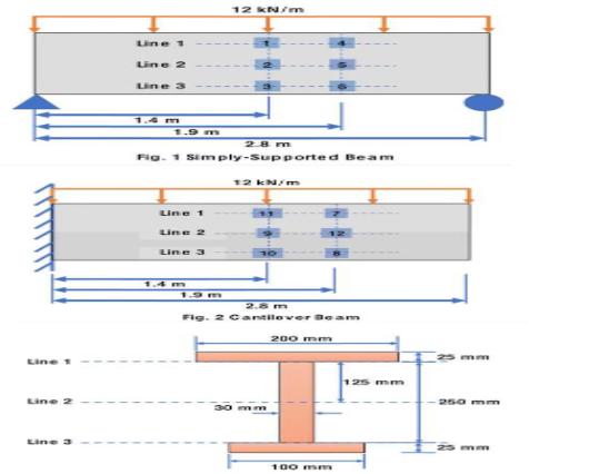
For the beams shown in Figs. 1 and 2, determine: 1 . Plane stress state 2. Principal stresses 3. Maximum in-plane she ar stress state
For the beams shown in Figs. 1 and 2, determine: 1
. Plane stress state
2. Principal stresses
3. Maximum in-plane she ar stress state with corresponding
4. Plot ALL stress states above
5. Plot Mohr Circle for ALL stress states above

Line Line 2 Line 3 Line 1 Line 2 Line 3 12 kN/m 1.4 m 1.9 m 28m Fig. 1 Simply-Supported Beam Line 1 Line 2 Line 3 12 kN/m 1.4 m 1.9 m 2.8 m Fig. 2 Cantilever Beam 30 200 mm 100 mm 125 mm 250 mm
Step by Step Solution
There are 3 Steps involved in it
Step: 1

Get Instant Access to Expert-Tailored Solutions
See step-by-step solutions with expert insights and AI powered tools for academic success
Step: 2

Step: 3

Ace Your Homework with AI
Get the answers you need in no time with our AI-driven, step-by-step assistance
Get StartedRecommended Textbook for
Mechanics of Materials
Authors: James M. Gere, Barry J. Goodno
7th edition
495438073, 978-0495438076
Students also viewed these Civil Engineering questions
Question
Answered: 1 week ago
Question
Answered: 1 week ago
Question
Answered: 1 week ago
Question
Answered: 1 week ago
Question
Answered: 1 week ago
Question
Answered: 1 week ago
Question
Answered: 1 week ago
Question
Answered: 1 week ago
Question
Answered: 1 week ago
Question
Answered: 1 week ago
Question
Answered: 1 week ago
Question
Answered: 1 week ago
Question
Answered: 1 week ago
Question
Answered: 1 week ago
Question
Answered: 1 week ago
Question
Answered: 1 week ago
Question
Answered: 1 week ago
Question
Answered: 1 week ago
Question
Answered: 1 week ago
Question
Answered: 1 week ago
Question
Answered: 1 week ago
View Answer in SolutionInn App


