Question
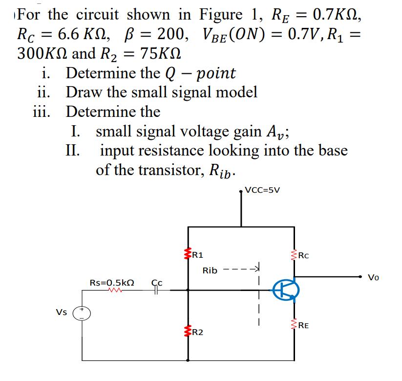
For the circuit shown in Figure 1, RE = 0.7KN, 0.7, Rc = 6.6 KN, = 200, VBE(ON) = 0.7V, R 300KN and R

For the circuit shown in Figure 1, RE = 0.7KN, 0.7, Rc = 6.6 KN, = 200, VBE(ON) = 0.7V, R 300KN and R = 75KN i. Determine the Q - point Draw the small signal model Determine the ii. iii. II. I. small signal voltage gain Av; input resistance looking into the base of the transistor, Rib. Vs Rs=0.5kQ Cc ww R1 Rib R2 VCC=5V ---> Rc RE = Vo
Step by Step Solution
3.41 Rating (157 Votes )
There are 3 Steps involved in it
Step: 1

Get Instant Access to Expert-Tailored Solutions
See step-by-step solutions with expert insights and AI powered tools for academic success
Step: 2

Step: 3

Ace Your Homework with AI
Get the answers you need in no time with our AI-driven, step-by-step assistance
Get StartedRecommended Textbook for
Income Tax Fundamentals 2013
Authors: Gerald E. Whittenburg, Martha Altus Buller, Steven L Gill
31st Edition
1111972516, 978-1285586618, 1285586611, 978-1285613109, 978-1111972516
Students also viewed these Accounting questions
Question
Answered: 1 week ago
Question
Answered: 1 week ago
Question
Answered: 1 week ago
Question
Answered: 1 week ago
Question
Answered: 1 week ago
Question
Answered: 1 week ago
Question
Answered: 1 week ago
Question
Answered: 1 week ago
Question
Answered: 1 week ago
Question
Answered: 1 week ago
Question
Answered: 1 week ago
Question
Answered: 1 week ago
Question
Answered: 1 week ago
Question
Answered: 1 week ago
Question
Answered: 1 week ago
Question
Answered: 1 week ago
Question
Answered: 1 week ago
Question
Answered: 1 week ago
Question
Answered: 1 week ago
Question
Answered: 1 week ago
Question
Answered: 1 week ago
Question
Answered: 1 week ago
View Answer in SolutionInn App


