Answered step by step
Verified Expert Solution
Question
1 Approved Answer
For the electrical circuit given in the following Figure 1 determine the following: 1) Determine the active equation relating the inductor current to the

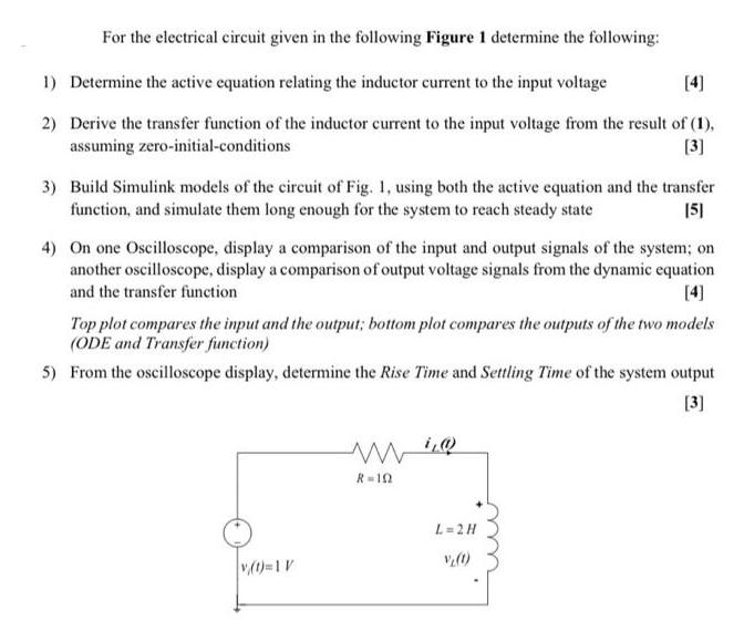
For the electrical circuit given in the following Figure 1 determine the following: 1) Determine the active equation relating the inductor current to the input voltage [4] 2) Derive the transfer function of the inductor current to the input voltage from the result of (1), assuming zero-initial-conditions [3] 3) Build Simulink models of the circuit of Fig. 1, using both the active equation and the transfer function, and simulate them long enough for the system to reach steady state [5] 4) On one Oscilloscope, display a comparison of the input and output signals of the system; on another oscilloscope, display a comparison of output voltage signals from the dynamic equation and the transfer function [4] Top plot compares the input and the output; bottom plot compares the outputs of the two models (ODE and Transfer function) 5) From the oscilloscope display, determine the Rise Time and Settling Time of the system output wi R=10 [3] v(t)=1 V L=2H V(t)
Step by Step Solution
There are 3 Steps involved in it
Step: 1
The image you sent contains a question about an electrical circuit along with steps to solve it The circuit consists of an inductor L resistor R and a voltage source vt The task requires determining t...
Get Instant Access to Expert-Tailored Solutions
See step-by-step solutions with expert insights and AI powered tools for academic success
Step: 2

Step: 3

Ace Your Homework with AI
Get the answers you need in no time with our AI-driven, step-by-step assistance
Get Started


