Answered step by step
Verified Expert Solution
Question
1 Approved Answer
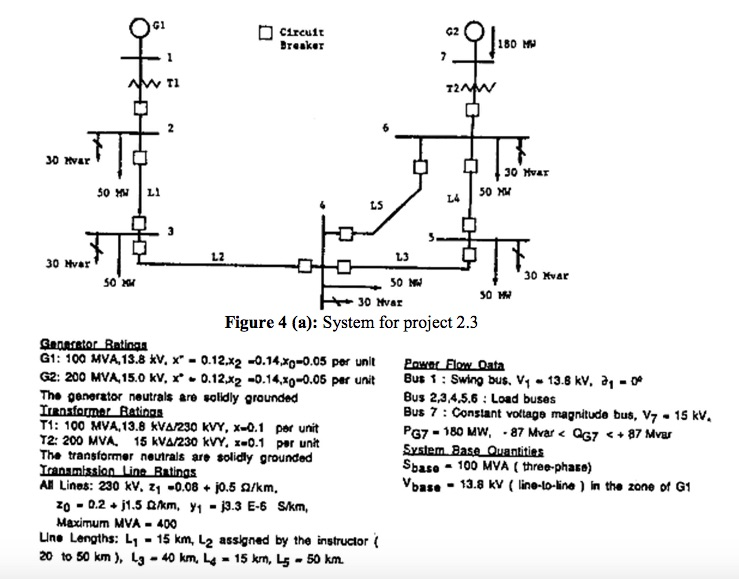
For the single-line diagram in figure below convert all positive-sequence impedance, load, and voltage data to per unit using the given system base quantities. Run
For the single-line diagram in figure below convert all positive-sequence impedance, load, and voltage data to per unit using the given system base quantities. Run the power flow program and obtain the bus, line, and transformer input/output voltages

30 Hvar 30 Hvar 50 MM L1 50 MM T1 12 Circuit Breaker LS Generator Batinga G1: 100 MVA, 13.8 kV, x 0.12.x2 -0.14.xg-0.05 per unit G2: 200 MVA,15.0 kV, x 0.12.x2 -0.14.0-0.05 per unit The generator neutrals are solidly grounded Transformer Ratings T1: 100 MVA, 13.8 KVA/230 kVY, X-0.1 per unit T2: 200 MVA. 15 KVA/230 kVY, x-0.1 per unit The transformer neutrals are solidly grounded Transmission Line Ratings All Lines: 230 kV, z -0.08 + j0.5 $2/km, zo 0.2+j1.5 km, yj3.3 E-6 S/km, Maximum MVA- 400 Line Lengths: L - 15 km, L assigned by the instructor ( 20 to 50 km), Lg 40 km, L 15 km, L5 - 50 km. - = L3 50 MW G2 L4 3 30 PHI Figure 4 (a): System for project 2.3 W - 180 MW 30 Hvar 50 MW 30 MW 30 Mvar Power Flow Data Bus 1: Swing bus. V 13.8 kV, a = 0 Bus 2,3,4,5.6: Load buses Bus 7: Constant voltage magnitude bus, V7 - 15 kV. PG7 = 180 MW, - 87 Mvar < QG7 < + 37 svar System Base Quantities Sbase 100 MVA (three-phase) Vbase 13.8 kV (line-to-line) in the zone of G1
Step by Step Solution
★★★★★
3.44 Rating (154 Votes )
There are 3 Steps involved in it
Step: 1

Get Instant Access to Expert-Tailored Solutions
See step-by-step solutions with expert insights and AI powered tools for academic success
Step: 2

Step: 3

Ace Your Homework with AI
Get the answers you need in no time with our AI-driven, step-by-step assistance
Get Started


