Answered step by step
Verified Expert Solution
Question
1 Approved Answer
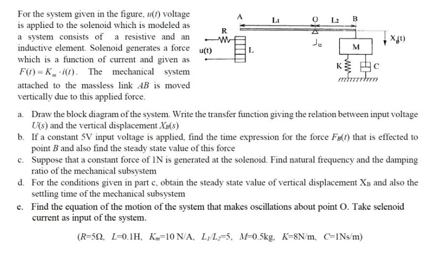
For the system given in the figure, u(t) voltage is applied to the solenoid which is modeled as a system consists of a resistive

For the system given in the figure, u(t) voltage is applied to the solenoid which is modeled as a system consists of a resistive and an inductive element. Solenoid generates a force u(t) which is a function of current and given as F(t)=K i(t). The mechanical system attached to the massless link AB is moved vertically due to this applied force. R W A L Li of Jo L2 B K M C arran X(t) a. Draw the block diagram of the system. Write the transfer function giving the relation between input voltage U(s) and the vertical displacement XB(S) b. If a constant 5V input voltage is applied, find the time expression for the force FB(t) that is effected to point B and also find the steady state value of this force c. Suppose that a constant force of IN is generated at the solenoid. Find natural frequency and the damping ratio of the mechanical subsystem d. For the conditions given in part c, obtain the steady state value of vertical displacement XB and also the settling time of the mechanical subsystem e. Find the equation of the motion of the system that makes oscillations about point O. Take selenoid current as input of the system. (R-50, L-0.1H, K-10 N/A, L/L-5, M-0.5kg, K-8N/m, C-INs/m)
Step by Step Solution
★★★★★
3.34 Rating (154 Votes )
There are 3 Steps involved in it
Step: 1
Solutions Step 1 a To draw the block diagram of the system we can represent the voltage source as the input the solenoid as a transfer function block ...
Get Instant Access to Expert-Tailored Solutions
See step-by-step solutions with expert insights and AI powered tools for academic success
Step: 2

Step: 3

Ace Your Homework with AI
Get the answers you need in no time with our AI-driven, step-by-step assistance
Get Started


