Question: For this assignment, you will write a program to find a maximum flow in a flow network. User Requirements The user is a start-up software
For this assignment, you will write a program to find a maximum flow in a flow network.
User Requirements
The user is a start-up software company that specializes in software for combinatorial optimization problems. One problem that can be used to model several combinatorial optimization problems is the maximum network flow problem, which is defined below. Your task is to write a program that reads the description of a flow network from a file and finds the maximum flow through that network. The program must produce an output file describing the maximum flow. Specifications for the input and output file formats are given below.
The Maximum Flow Problem
Informally, we can think of a flow network as a network of pipes of varying diameters. Water enters the network at a specified source and exits the network at a specified sink. The maximum flow problem is then to determine how much water can flow through the entire network.
More formally, a flow network is a directed graph containing:
a node designated as the source;
a different node designated as the sink; and
an integer capacity for each edge.
For example, the following is a flow network:
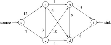
A flow for a flow network is an assignment of values to the edges such that:
each value is no more than the capacity of the edge; and
for each node other than the source and the sink, the sum of the values on the incoming edges is equal to the sum of the values on the outgoing edges.
For example, the following is a flow for the above flow network:
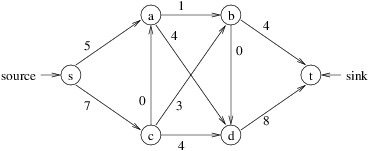
The value of a flow is the net flow entering the sink - i.e., the total flow entering the sink, minus the total flow leaving the sink. Thus, the above flow has a value of 12. (Note that the net flow entering the sink will always equal the net flow leaving the source.) The maximum flow problem is to find the flow with maximum value for a given flow network. The flow shown above is not the maximum, as the following flow has a value of 14:
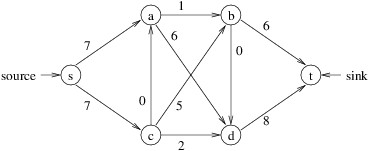
This flow is a maximum flow for the given flow network.
File Formats
Both input and output files will be in comma-separated-value format. The first line of the input file will contain two strings giving the source node and the sink node for the flow network. Each successive line will contain three values describing an edge of the flow network:
a string giving the source node of the edge;
a string giving the destination node of the edge;
a positive integer giving the capacity of the edge.
The first line of the output file will contain an integer giving the maximum flow for the flow network. Each successive line will contain three values describing the flow on an edge of the flow network:
a string giving the source node of the edge;
a string giving the destination node of the edge;
a positive integer giving the flow on the edge.
Edges that have no flow will not be included in the output file.
Starting the Assignment
Create a GitHub repository using this URL (Links to an external site.)Links to an external site.. The Visual Studio Solution in this repository contains a new Windows Forms Application with the Ksu.Cis300.Graphsand Ksu.Cis300.LinkedListLibrary projects from the model solution to Lab Assignment 35 added. The repository also contains an executable hw6.exe illustrating correct execution of the program and a folder Data containing several test data files.
User Interface
The program should display a GUI resembling the following:
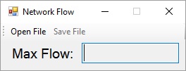
The "Save File" button on the ToolStrip should be initially disabled, and the TextBoxshould be read-only (see Homework Assignment 1 to review how to set up a ToolStrip). It should be impossible to maximize or otherwise re-size the window.
If the user clicks the "Open File" button, an OpenFileDialog should be displayed. There should be no initial file name in this dialog. Its filter should display by default, "CSV files (*.csv)", and show only files with the suffix ".csv". The only other option for the filter should be "All files (*.*)", showing all files. If the user selects a file, the program should attempt to read a flow network from the selected file and find a maximum flow. It should display the value of the maximum flow in the TextBox and enable the "Save File" button, which should remain enabled thereafter.
If the user clicks the "Save File" button, a SaveFileDialog should be displayed. There should be no initial file name in this dialog, and its filter should be the same as in the OpenFileDialog above. If the user selects a file, the program should attempt to write the current maximum flow to the selected file according to the output file format specified under "File formats" above. Once the file is successfully written, it should display a MessageBox containing the message, "File written."
Exception Handling
The program should check explicitly for the following input errors:
The input file is empty. In this case, it should display a MessageBox containing the message, "The input file is empty."
Not enough fields are present on some line of input. If line 1 contains too few fields, it should display a MessageBox containing the message, "Line 1 does not contain 2 fields." If a subsequent line contains too few fields, it should display a MessageBoxcontaining the message, "Line n does not contain 3 fields." where n is the number of the line with the error.
The source and sink nodes are the same. It should then display a MessageBoxcontaining the message, "The source and sink nodes must be different."
The third field of some line after the first cannot be converted to an integer. It should then display a MessageBox containing the message, "In line n, the capacity is not an integer." where n is the number of the line with the error (the first line of the file is line 1).
The capacity of an edge is not positive (note: 0 is not positive). It should then display a MessageBox containing the message, "In line n, the capacity is not positive." where n is the number of the line with the error.
Some edge occurs more than once. It should then display a MessageBox containing the message, "An edge can be included only once."
The source and destination nodes for some edge are the same. It should then display a MessageBox containing the message, "The source and destination of each edge must be distinct."
Note that in each of the above cases, an exception is not displayed - only a sentence describing the error. If any other exceptions (not caused by programmer error) are thrown during the reading or writing of a file, the program should display a MessageBoxcontaining the exception. If any error condition occurs, any pre-existing network flow must be retained so that a subsequent attempt to write the output will save it. Furthermore, if any error occurs in reading the input, the value displayed for the maximum flow should remain unchanged, and the "Save File" button should remain in the same state (i.e., either enabled or disabled).
Maximum Flow Algorithm
The algorithm for finding a maximum flow will maintain two directed graphs. The first of these will represent the current flow. It will contain all the nodes from the input graph. Its edges will be the input graph's edges that have been assigned a positive flow. The data associated with an edge will be the flow that it has been assigned. In order to simplify the algorithm, we will stipulate that if there are edges (u, v) and (v, u) in the input graph, at most one of these edges will have a positive flow in the flow graph (as there is nothing to be gained by having flow in both directions). The algorithm will progress by repeatedly increasing the flow until it is impossible to increase it any further.
In order to determine whether the current flow can be increased, a second graph, known as the residual graph, will be used. This graph will be derived from the input graph with capacities updated to reflect the flow that has already been assigned to the edges. In deriving this residual graph, however, we must be careful not to lose any information from the input graph, in case some of the edges have been assigned too much flow.
For example, consider the first flow (with value 12) shown for the example flow network above. In this flow, the edges (a, b), (s, c), (c, d), and (d, t) have been filled to capacity. Because there is no path from s to t that does not include at least one of these edges, it would at first seem that this flow must be the maximum. However, the second flow, which was constructed in part by reducing the flow on edge (c, d), is larger.
The residual graph therefore needs to incorporate the fact that we can reduce flow on certain edges. Putting it another way, we incorporate the fact that a certain amount of flow can be placed in the opposite direction of certain edges. Specifically, we define the nodes of the residual graph to be the same as those in the input graph. For each edge (u, v) in the input graph, we then include the following edge(s) in the residual graph:
If there is no flow on either (u, v) or (v, u) (if this edge exists), then (u, v) will retain its original capacity from the input graph.
If there is a positive flow of k on (u, v), then its capacity is decreased from its original capacity by k (removing the edge if this brings its capacity to 0), and the capacity of (v, u) is increased by k. If there is no edge (v, u) in the input graph, this edge with capacity k is added.
Thus, the residual graph for the first flow above is:
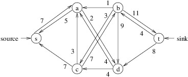
The edge (s, a) originally had a capacity of 12, but a flow of 5 on this edge has reduced its capacity to 7 and added an edge (a, s) with a capacity of 5. Edge (s, c) initially had a capacity of 7, but a flow of 7 on this edge reduced its capacity to 0 (thus removing it) and added an edge (c, s) with a capacity of 7. Edge (c, a) initially had a capacity of 3, and no flow has been placed on this edge; hence, its original capacity of 3 remains. The remainder of the residual graph is constructed similarly.
Notice that in the residual graph above, there is a path from s to t: s, a, d, c, b, t. The minimum capacity of any of the edges on this path is 2; hence, we can add a flow of 2 to each edge in this path (called an augmenting path). Note that the flow added along (d, c) is in the opposite direction of the flow of 4 that already exists along (c, d). To add this flow, we simply reduce the flow along (c, d) by 2. The result is the flow with value 14 shown above, and the resulting residual graph is:
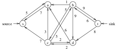
Note that there is now no path from s to t in this residual graph. When no path exists from the source to the sink, we know that the flow we have found has a maximum value.
Putting it all together, the algorithm we will use, known as the Edmonds-Karp algorithm, is as follows:
Initialize the residual graph to the given flow network.
Initialize the flow graph to a graph having the same nodes as the residual graph, but no edges.
Initialize the value of the flow to 0.
While there is a path from the source to the sink in the residual graph:
Find a shortest such path (i.e., fewest edges) using breadth-first search.
Find the minimum capacity in the residual graph along this path.
Increase the value of the flow by this minimum capacity.
Update the flow graph and the residual graph by adding a flow of the minimum capacity along the path.
Software Architecture
Below is a class diagram showing the relationships between the classes you need from the three projects:
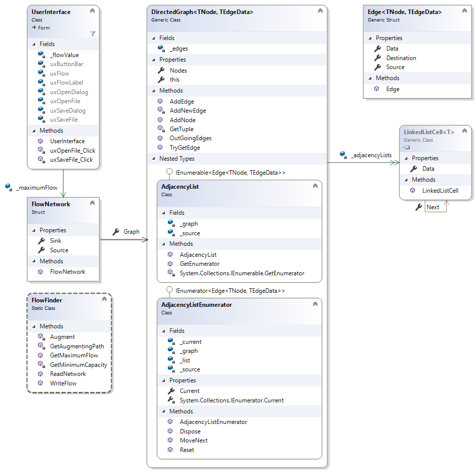
FlowNetwork is an immutable structure in the Ksu.Cis300.NetworkFlow project. It stores the graph and the source and sink nodes for a flow network. FlowFinder is a static class in the Ksu.Cis300.NetworkFlow project. It contains various methods for reading and writing flow graphs and finding a maximum flow. You will need to modify the DirectedGraph
Coding Requirements
Coding requirements for each of the classes that you need to add or change are discussed in what follows.
The DirectedGraph
To this class, you will need to add two public methods and a public indexer (Links to an external site.)Links to an external site.. You will also need to modify the AddEdge and GetTuple methods. These changes (specifically the addition of the indexer) will allow edge data to be modified; however, there will still be no way to remove edges. Instead, because all capacities and flows on edges will be positive, you will be able to denote a "removed" edge by setting its data to 0. Requirements for the methods and the indexer are described in what follows.
The GetTuple method
The message to be displayed when the source and destination nodes of an edge are the same (see under "Exception Handling" above) needs to be included in the exception that is thrown in this case.
The AddEdge method
The message to be displayed when some edge occurs more than once should (see under "Exception Handling" above) needs to be included in the exception that is thrown in this case.
A method to add a node
This method should take as its only parameter the node to be added, and it should return nothing. To add the node, it can add it as a key to the _adjacencyLists dictionary, with null as its associated value.
A method to obtain the data item associated with an edge
This method should take the following parameters:
the source node of an edge;
the destination node of an edge; and
an out parameter for the data item associated with the edge from the source to the destination.
It should return a bool indicating whether there is an edge from the source to the destination. If so, the out parameter should be set to the data item associated with that edge; otherwise, the out parameter should be set to the default value for this type. You can accomplish all of this by using the TryGetValue method of the _edges dictionary.
An indexer
This indexer will allow the user to get or modify the data item associated with an edge by using its source and destination nodes as indices. For example, if graph refers to a DirectedGraph
The type of this indexer should be TEdgeData. It will need as its parameters the source and destination nodes. It will need both a get accessor and a set accessor. The get accessor should return the data item associated with the edge from the source to the destination, or throw a KeyNotFoundException if there is no such edge. You can accomplish this by indexing into the _edges dictionary with a Tuple formed from the source and destination nodes. The set accessor should set the data item associated with this edge to the value given via the value keyword. If this edge does not exist, it should be added, along with the given source and/or destination nodes as necessary. If either the source or destination is null, it should throw an ArgumentNullException. If the two nodes are equal, it should throw an ArgumentException. You can pattern your code after the AddEdge method, but instead of throwing an exception if the edge already exists, assign the given value to the edge in the _edges dictionary (the _adjacencyLists dictionary won't change in this case).
The FlowNetwork Structure
This should be a structure, not a class. It should contain the following public properties, each with get accessors:
the source node (a string);
the sink node (a string); and
the graph (a DirectedGraph
It should also have a public constructor that takes values to initialize the the first two of these properties. It should also initialize the graph to a new instance, and it should add the given source and sink nodes to this graph.
Note that although the graph property cannot be set, the contents of the graph may be modified.
The FlowFinder Class
This class will need three public methods and three private methods. Because the class is static, these methods will all need to be static.
A public method to read the input file
This method should take as its only parameter the name of the input file, and it should return the FlowNetwork read from the file. This method should not display any MessageBoxes, but should instead throw exceptions for the calling method to handle. All of the explicit error checking, except for what is done in the DirectedGraph
A private method to find an augmenting path
This method should take as its only parameter a FlowNetwork giving the residual graph. It should return a dictionary of path information, as in Lab Assignment 34, giving a shortest path from the source to the sink in the residual graph. It should do a breadth-first search (see Lab Assignment 34) to find the shortest path. Use the Queue
A private method to find the minimum capacity on an augmenting path
This method should take as its parameters a dictionary of path information and a FlowNetwork representing a residual graph. It should return the minimum capacity of any edge on the path (given in the dictionary) from the source to the sink. It should use the dictionary to retrace the path backwards from the sink to the source, and for each edge, use the residual graph to obtain that edge's capacity.
A private method to augment the flow
This method should take the following parameters:
a FlowNetwork representing a residual graph;
a FlowNetwork representing a flow;
a dictionary of path information; and
the amount of flow to be added.
It should return nothing. As in the above method, it should retrace the path backwards from the sink to the source. For each edge (u, v) along this path, it should:
Decrease the capacity of (u, v) in the residual graph by the amount of flow being added.
Increase the capacity of (v, u) in the residual graph by the amount of flow being added.
If there is positive flow on (v, u), decrease this flow by the minimum of this flow and the flow being added.
If the flow being added is greater than the amount that the flow on (v, u) was decreased in the above step, add the difference of these values to the flow on (u, v).
For example, suppose we are adding a flow of 5, and that (u, v) has a capacity of 8, (v, u) has a capacity of 1, and there is a flow of 2 on (v, u). Then we decrease the capacity of (u, v) to 3, increase the capacity of (v, u) to 6, decrease the flow on (v, u) to 0 (in effect, removing this edge), and increase the flow on (u, v) to 3 (adding this edge in the process).
Be careful in getting edge data, as not all of the edges are guaranteed to exist (the edges whose capacities are decreased will always exist in the residual graph).
A public method to find a maximum flow
This method should take as its parameters a FlowNetwork and an out int parameter through which the value of the maximum flow will be returned. It should return a FlowNetwork giving the maximum flow. It should implement the algorithm described under "Maximum Flow Algorithm" above, making appropriate use of the above methods. While the algorithm indicates that the flow should be initialized to contain the same edges as in the given FlowNetwork, it is easiest to construct a FlowNetwork with the same source and sink, and allow the other nodes to be added automatically as edges are added (if some nodes don't get added, they will have no incoming or outgoing edges in the flow, and hence would not appear in the output). It also will be easiest to set up the loop as an infinite loop, with a return from inside the loop whenever no augmenting path is found.
A public method to write the output file
This method should take the following parameters:
the name of the file to be written;
a FlowNetwork giving the flow; and
the value of the flow.
It should return nothing. It should first write the value of the maximum flow to the file, then iterate through all the edges in the flow graph, writing the source, destination, and data for each edge that has positive data. It does not need to do any exception handling.
The UserInterface Class
This class will need two private fields in addition to the graphical controls:
a FlowNetwork giving the maximum flow; and
an int giving the value of the maximum flow.
It will also need two event handlers. The requirements for these methods are described in what follows.
The event handler for the "Open File" button
This event handler is responsible for showing the OpenFileDialog, and if the user selects a file, reading the file, finding a maximum flow using the algorithm given under "Maximum Flow Algorithm" above, displaying the value of the maximum flow on the GUI, and enabling the "Save File" button. It should make appropriate use of the methods in FlowFinder. All of the exception handling for reading and processing the file should be done here. You will need more than one catch-block for your try-catch - one for each exception type that you throw to display a specific message, followed by one to catch all remaining exceptions (see the section, "Exception Handling" (Links to an external site.)Links to an external site., for details on how this is done). You can obtain the message from an exception via its Message (Links to an external site.)Links to an external site.propery.
The event handler for the "Save File" button
This event handler is responsible for showing the SaveFileDialog, and if the user selects a file, writing the maximum flow to that file using the above method and displaying the "File written." message. The exception handling for writing the output should be done here.
Testing and Performance
The Data folder contains several test data files. Its subfolder Output contains the output files produced by the posted executable for those test files that do not contain errors. Your output files should be exactly the same. Note that the first line of an output file gives the value of the maximum flow, which is the value that should be displayed by your GUI when the input file is opened.
Test1.csv is the flow network given in the example under "The Maximum Flow Problem" above. Test10.csv contains only a source and a sink, with no edges - your program should find a maximum flow of 0 on this file, and successfully write the flow graph. Test11.csv and Test12.csv are derived from OpenStreetMap data with random edge weights. The remaining files contain various input errors that your program should be able to recognize. They should produce the following messages:
Test2.csv: "Line 1 does not contain 2 fields."
Test3.csv: "Line 4 does not contain 3 fields."
Test4.csv: "The source and sink nodes must be different."
Test5.csv: "In line 6, the capacity is not an integer."
Test6.csv: "In line 8, the capacity is not positive."
Test7.csv: "An edge can be included only once."
Test8.csv: "The source and destination of each edge must be distinct."
Test9.csv: "The input file is empty."
The performance of your program should be within a factor of 2 of the sample executable.
12 9 source 12 9 source
Step by Step Solution
There are 3 Steps involved in it

Get step-by-step solutions from verified subject matter experts


