Question
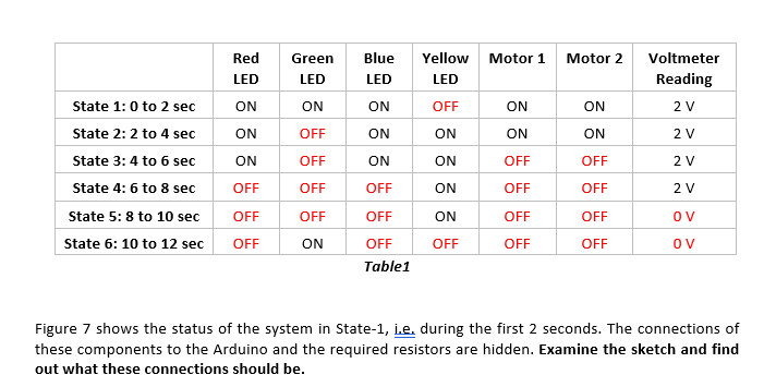
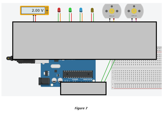
Four LEDs, two DC Motors and a voltmeter (along with appropriate resistors as needed) are connected to an Arduino. The following code will be executed
Four LEDs, two DC Motors and a voltmeter (along with appropriate resistors as needed) are connected to an Arduino. The following code will be executed on the Arduino.
Arduino Uno Code:
void setup()
{
pinMode(12, OUTPUT);
pinMode(4, OUTPUT);
pinMode(2, OUTPUT);
pinMode(13, OUTPUT);
digitalWrite(12, HIGH);
digitalWrite(4, HIGH);
digitalWrite(2, HIGH);
digitalWrite(13, HIGH);
}
void loop()
{
delay(2000);
digitalWrite(4, LOW);
delay(2000);
digitalWrite(2, LOW);
delay(2000);
digitalWrite(12, LOW);
delay(2000);
digitalWrite(13, LOW);
delay(2000);
digitalWrite(4, HIGH);
delay(2000);
digitalWrite(2, HIGH);
digitalWrite(13, HIGH);
digitalWrite(12, HIGH);
}
When the sketch is run, the system will go through a 12-second cycle as shown in Table 1 and continue repeating the pattern. In the ON state, the LEDs can have any brightness as long theyre visibly ON. When turned on, Motor-1 rotates only clockwise (with a positive rpm) and Motor-2 rotates only counter-clockwise (with a negative rpm). The voltmeter reading should be close to 2 V if not exactly 2 V (Hint: use a voltage divider).


Once you determine what the connections are, run the sketch and confirm that it properly goes through the six states periodically as listed in Table 1.
In your report, include a clear screenshot of the circuit connections when the system is in State-2. Specify the resistor values you used.
Step by Step Solution
There are 3 Steps involved in it
Step: 1

Get Instant Access to Expert-Tailored Solutions
See step-by-step solutions with expert insights and AI powered tools for academic success
Step: 2

Step: 3

Ace Your Homework with AI
Get the answers you need in no time with our AI-driven, step-by-step assistance
Get Started


