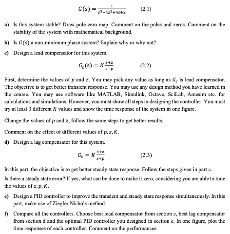
G(s) 1 $3+482 +45+2 (2.1) a) Is this system stable? Draw pole-zero map. Comment on the poles and zeros. Comment on the stability of the system with mathematical background. b) Is G(s) a non-minimum phase system? Explain why or why not? c) Design a lead compensator for this system. Ge(s) = (2.2) S+p 5+2 First, determine the values of p and z. You may pick any value as long as Ge is lead compensator. The objective is to get better transient response. You may use any design method you have learned in the course. You may use software like MATLAB, Simulink, Octave, SciLab, Amesim etc. for calculations and simulations. However, you must show all steps in designing the controller. You must try at least 3 different K values and show the time response of the system in one figure. Change the values of p and z, follow the same steps to get better results. Comment on the effect of different values of p,2,K. d) Design a lag compensator for this system. GE = K (2.3) s+p In this part, the objective is to get better steady state response. Follow the steps given in part c. Is there a steady state error? If yes, what can be done to make it zero, considering you are able to tune the values of 2,p, K. c) Design a PID controller to improve the transient and steady state response simultaneously. In this part, make use of Ziegler Nichols method. 1) Compare all the controllers. Choose best lead compensator from section c, best lag compensator from section d and the optimal PID controller you designed in section e. In one figure, plot the time responses of each controller. Comment on the performances. G(s) 1 $3+482 +45+2 (2.1) a) Is this system stable? Draw pole-zero map. Comment on the poles and zeros. Comment on the stability of the system with mathematical background. b) Is G(s) a non-minimum phase system? Explain why or why not? c) Design a lead compensator for this system. Ge(s) = (2.2) S+p 5+2 First, determine the values of p and z. You may pick any value as long as Ge is lead compensator. The objective is to get better transient response. You may use any design method you have learned in the course. You may use software like MATLAB, Simulink, Octave, SciLab, Amesim etc. for calculations and simulations. However, you must show all steps in designing the controller. You must try at least 3 different K values and show the time response of the system in one figure. Change the values of p and z, follow the same steps to get better results. Comment on the effect of different values of p,2,K. d) Design a lag compensator for this system. GE = K (2.3) s+p In this part, the objective is to get better steady state response. Follow the steps given in part c. Is there a steady state error? If yes, what can be done to make it zero, considering you are able to tune the values of 2,p, K. c) Design a PID controller to improve the transient and steady state response simultaneously. In this part, make use of Ziegler Nichols method. 1) Compare all the controllers. Choose best lead compensator from section c, best lag compensator from section d and the optimal PID controller you designed in section e. In one figure, plot the time responses of each controller. Comment on the performances


