Guides Battery Safety: 6.0 V only; leads should be unattached to breadboard when not in use; leads should never be connected to each other. unattached
Guides
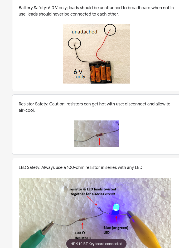
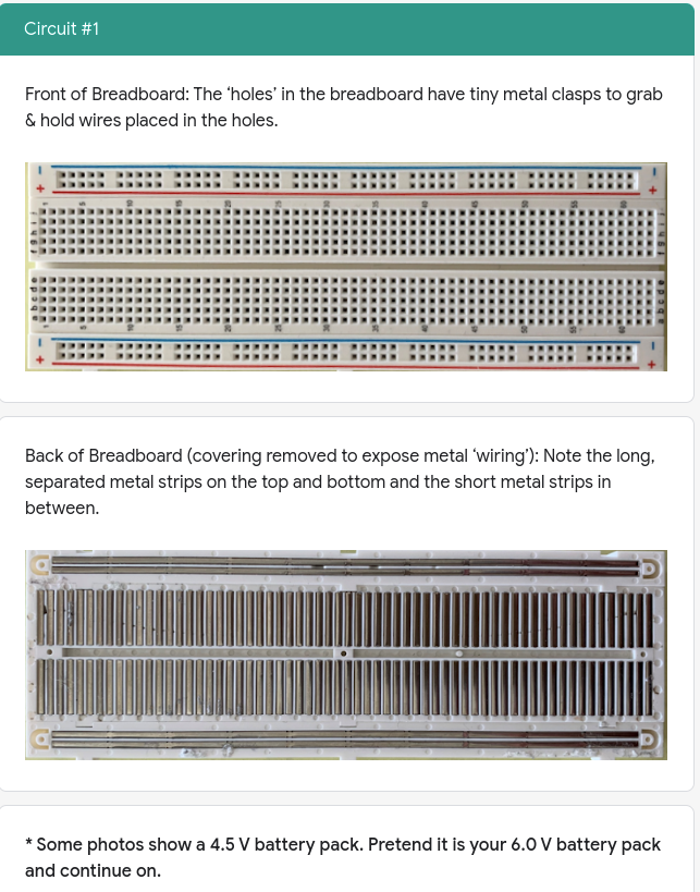
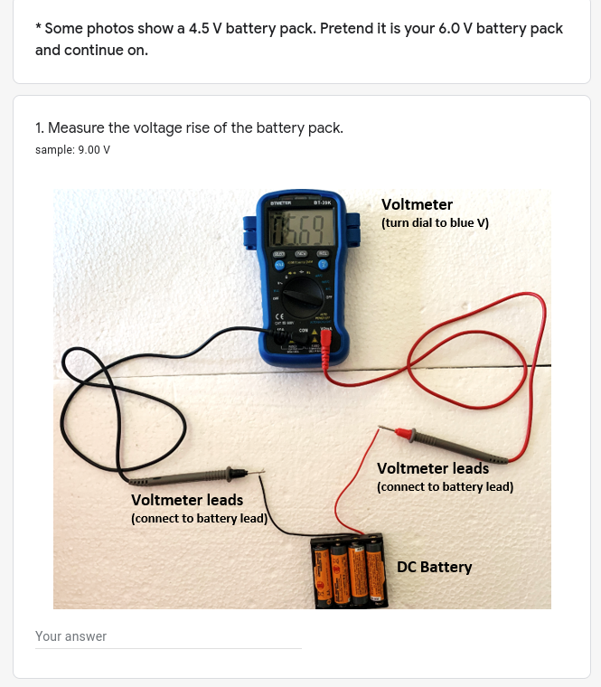
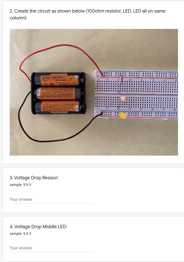
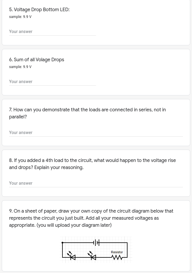
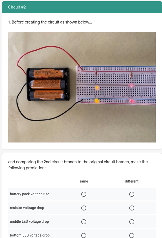
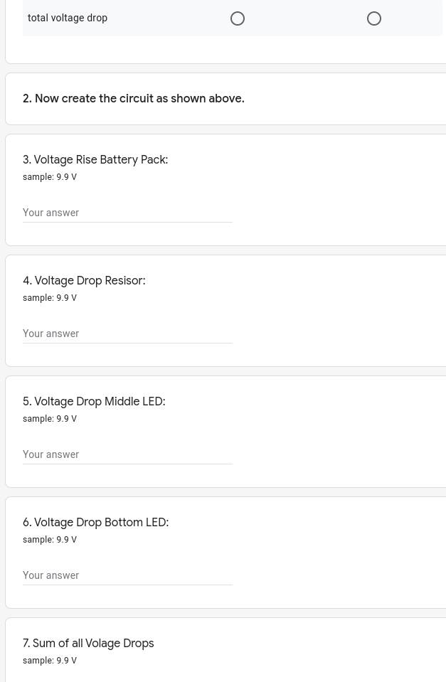
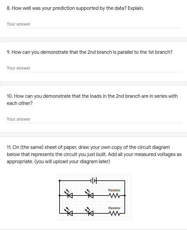
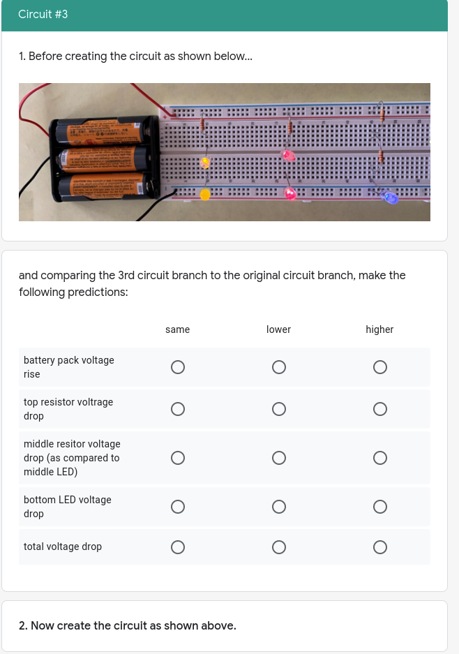
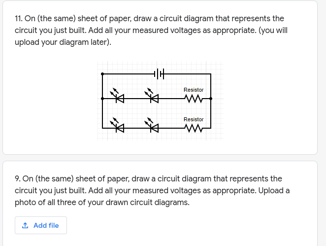
Battery Safety: 6.0 V only; leads should be unattached to breadboard when not in use; leads should never be connected to each other. unattached 6 V only Resistor Safety: Caution: resistors can get hot with use; disconnect and allow to air-cool. LED Safety: Always use a 100-ohm resistor in series with any LED resistor & LED leads twisted together for a series circuit Blue (or green) 100 Q LED Resistor 1 HP 910 BT Keyboard connectedCircuit #1 Front of Breadboard: The 'holes' in the breadboard have tiny metal clasps to grab & hold wires placed in the holes. + Back of Breadboard (covering removed to expose metal 'wiring'): Note the long, separated metal strips on the top and bottom and the short metal strips in between. *Some photos show a 4.5 V battery pack. Pretend it is your 6.0 V battery pack and continue on.* Some photos show a 4.5 V battery pack. Pretend it is your 6.0 V battery pack and continue on. 1. Measure the voltage rise of the battery pack. sample: 9.00 V BTMETER Voltmeter (turn dial to blue V) Voltmeter leads [ connect to battery lead) Voltmeter leads (connect to battery lead) DC Battery Your answer2. Create the circuit as shown below [lohm resistor. LED. LED all on same column] 3. Voltage Drop Resisor: sample: 9.9 9' Your answer 4. Voltage Drop Middle LED: sample: 9.9 9' \"four answer 5. Voltage Drop Bottom LED: sample: 9.9 V Your answer 6. Sum of all Volage Drops sample: 9.9 V Your answer 7. How can you demonstrate that the loads are connected in series, not in parallel? Your answer 8. If you added a 4th load to the circuit, what would happen to the voltage rise and drops? Explain your reasoning. Your answer 9. On a sheet of paper, draw your own copy of the circuit diagram below that represents the circuit you just built. Add all your measured voltages as appropriate. (you will upload your diagram later) ResistorCircuit #2 1. Before creating the circuit as shown below.. and comparing the 2nd circuit branch to the original circuit branch, make the following predictions: same different battery pack voltage rise O resistor voltrage drop O o OOO middle LED voltage drop O bottom LED voltage drop Ototal voltage drop O O 2. Now create the circuit as shown above. 3. Voltage Rise Battery Pack: sample: 9.9 V Your answer 4. Voltage Drop Resisor: sample: 9.9 V Your answer 5. Voltage Drop Middle LED: sample: 9.9 V Your answer 6. Voltage Drop Bottom LED: sample: 9.9 V Your answer 7. Sum of all Volage Drops sample: 9.9 VB. How well was your prediction supported by the data? Explain. 'r'our answer 9. How can you demonstrate that the 2nd branch is parallel to the 1st branch? Your answer 10. How can you demonstrate that the loads in the 2nd branch are in series with each other? \"four answer 11. [in {the same} sheet of paper, draw your own copy of the circuit diagram below that represents the circuit you just built. Add all your measured 1\"voltages as appropriate. {you will upload your diagram later} Circuit #3 1. Before creating the circuit as shown below... and comparing the 3rd circuit branch to the original circuit branch, make the following predictions: same lower higher battery pack voltage rise O O O top resistor voltrage drop O O O middle resitor voltage drop (as compared to O O O middle LED) bottom LED voltage drop O O O total voltage drop O O O 2. Now create the circuit as shown above.3. Voltage Rise Battery Pack: sample: 9.9 V Your answer 4. Voltage Drop Top Resisor: sample: 9.9 V Your answer 5. Voltage Drop Middle Resistor: sample: 9.9 V Your answer 6. Voltage Drop Bottom LED: sample: 9.9 V Your answer 7. Sum of all Volage Drops sample: 9.9 V Your answer 8. How well was your prediction supported by the data? Explain. Your answer11. On {the same) sheet of paper, draw a circuit diagram that represents the circuit you just built. Add all your measured voltages as appropriate. (you will upload your diagram later}. 9. On (the same} sheet of paper, draw a circuit diagram that represents the circuit you just built. Add all your measured voltages as appropriate. Upload a photo of all three of your drawn eireuit diagrams. .12 Add file
Step by Step Solution
There are 3 Steps involved in it
Step: 1
Get Instant Access to Expert-Tailored Solutions
See step-by-step solutions with expert insights and AI powered tools for academic success
Step: 2
Step: 3
Ace Your Homework with AI
Get the answers you need in no time with our AI-driven, step-by-step assistance