Answered step by step
Verified Expert Solution
Question
1 Approved Answer
hear Force in kips for the shown beam .50 kips, w = 1.75 k/ft. diagrams and formulas to calculate the required values. The diagrams
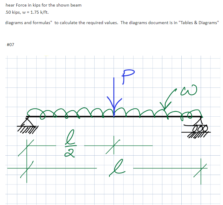
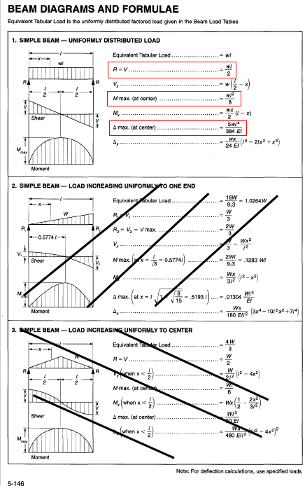
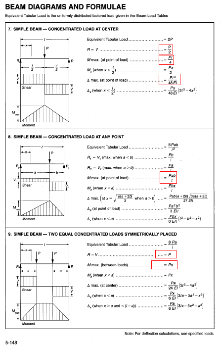
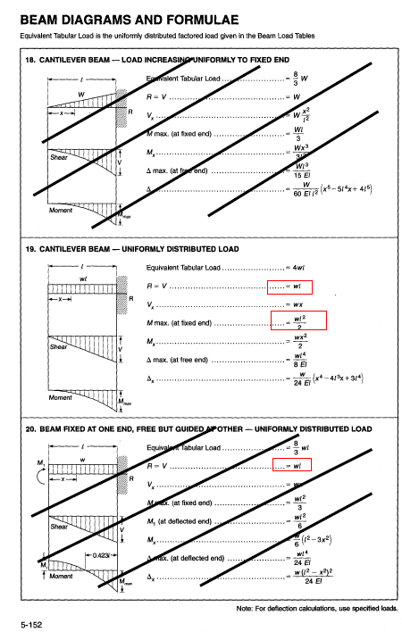
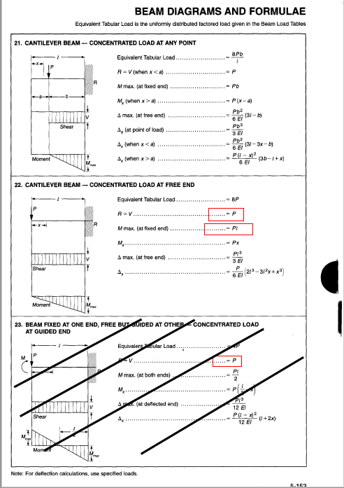
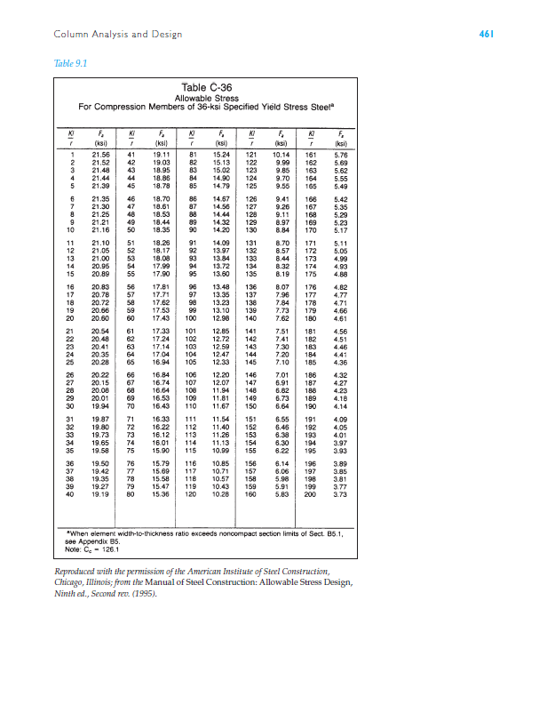
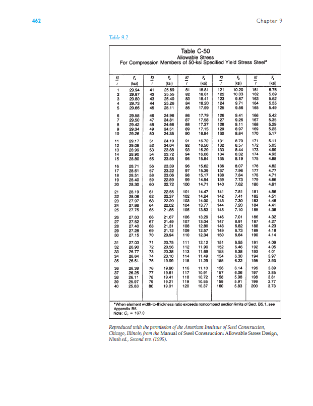
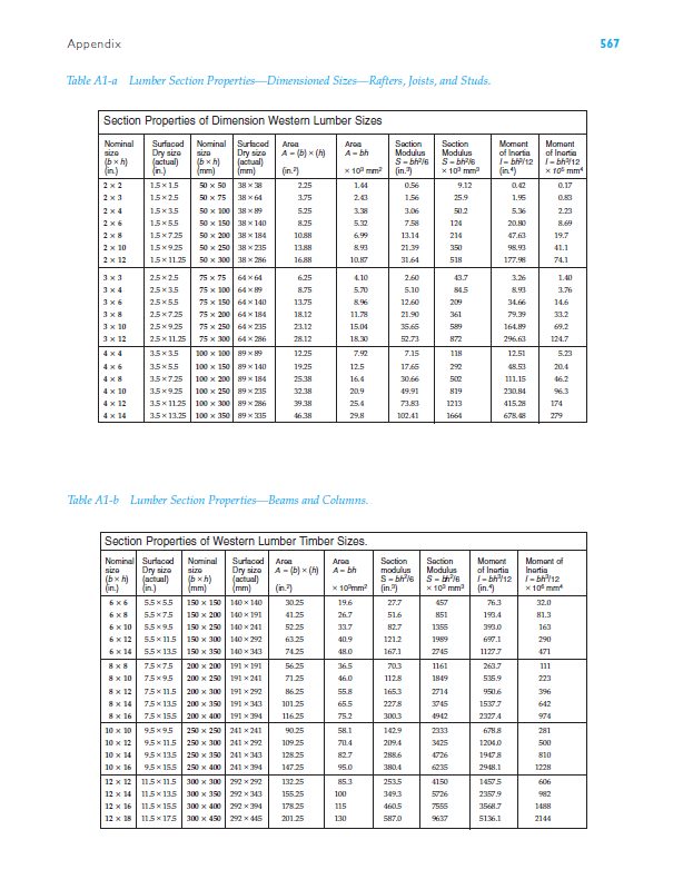
hear Force in kips for the shown beam .50 kips, w = 1.75 k/ft. diagrams and formulas" to calculate the required values. The diagrams document is in "Tables & Diagrams" #07 2 BEAM DIAGRAMS AND FORMULAE Equivalent Tabular Load is the uniformly distributed factored load given in the Beam Load Tables 1. SIMPLE BEAM - UNIFORMLY DISTRIBUTED LOAD W! Equivalent Tabular Load.. Wi WI A-V.. 2 M max. (at center) My wx (1-x) 2 Shear A max. (at center). 5w4 384 El WX 24 El -2x+x) Moment 2. SIMPLE BEAM-LOAD INCREASING UNIFORMLY TO ONE END R -0.57741- Shear Moment W Equivalent abular Load. 16W 9,3 -1.0264W W 3 R 2W R-V-V max..... Wx Vx M max. (x=0.57741) 3 2WI = .1283 W 9.3 Wx 3/2 8 A max. 5193 / 15 31).. .01304 Ax Wx 180 Ell (3x-101x+714) 3. SIMPLE BEAM-LOAD INCREASING UNIFORMLY TO CENTER 5-146 4W Equivalent Tawar Load..... R-V. 2 W A {when x < = (12- 4x) 212 W M max. (at came M(when x 2x2 Wx WI Shear A max. (at center) El Wx when x BEAM DIAGRAMS AND FORMULAE Equivalent Tabular Load is the uniformly distributed factored load given in the Beam Load Tables 7. SIMPLE BEAM-CONCENTRATED LOAD AT CENTER R R Equivalent Tabular Load 2P R-V M max. (at point of load) My (when x < P 2 PL 4 b). A (at point of load) Moment A, (when x BEAM DIAGRAMS AND FORMULAE Equivalent Tabular Load is the uniformly distributed factored load given in the Beam Load Tables 18. CANTILEVER BEAM-LOAD INCREASING UNIFORMLY TO FIXED END W R Evalent Tabular Load.... R-V W w Mmax. (at fixed end). W WI 3 Wx 312 Shear Wia A max. (at frend) 15 E W 60 ET2 Moment 19. CANTILEVER BEAM - UNIFORMLY DISTRIBUTED LOAD Equivalent Tabular Load... R-V. 4wi WX M max. (at fixed end) 2 My- Shear wx2 2 A max. (at free end) 8 E Moment W 24 El (x4-413x+314) 20. BEAM FIXED AT ONE END, FREE BUT GUIDED APOTHER-UNIFORMLY DISTRIBUTED LOAD M. Equivale Tabular Load R-V wi w! 5-152 Shear Moment Max (at fixed end) wiz M, (at deflected end). 3 w2 (12-3x) -0.423- Aax. (at deflected end) 24 E Ax w(12-x2)2 24 El Note: For deflection calculations, use specified loads. BEAM DIAGRAMS AND FORMULAE Equivalent Tabular Load is the uniformly distributed factored load given in the Beam Load Tables 21. CANTILEVER BEAM-CONCENTRATED LOAD AT ANY POINT Moment Equivalent Tabular Load... 8Pb R-V (when x a) P(x-a) Pb A max. (at free end) (31-b) 6 El Shear Pb 4, (at point of load) 3 El Pb A, (when x a) PU-2 6 El -(3b-1+x) 22. CANTILEVER BEAM - CONCENTRATED LOAD AT FREE END Equivalent Tabular Load.. BP R=V.. P M max. (at fixed end) Pl Px P13 A max. (at free end) 3 El P Shear Ax 6 El (21-312x+x) Moment 23. BEAM FIXED AT ONE END, FREE BUT GUIDED AT OTHER CONCENTRATED LOAD AT GUIDED END Shear Mome Equivalent dular Load. V. M max. (at both ends) P Pia A(at deflected end) Note: For deflection calculations, use specified loads. 12 ET P(1-x)2 12 El -(1+2x) 5.159 Column Analysis and Design Table 9.1 Table C-36 Allowable Stress For Compression Members of 36-ksi Specified Yield Stress Steel" K 81- F (ksi) 16 24 25 31 38 CARGO 8 58838 85889 12349 21.56 21.52 21.48 21.44 5 7 21.39 6 21.35 46 21.30 8 21.25 9 21.21 10 21.16 11 21.10 12 21.05 13 21.00 14 15 20.95 20.89 20.83 17 20.78 18 20.72 19 20.66 20 20.60 21 20.54 22 20.48 23 20.41 20.35 20.28 26 20.22 27 20.15 20.08 30 20.01 19.94 19.87 19.80 19.73 19.65 19.58 36 19.50 37 19.42 19.35 39 19.27 1998 238 86388 8838 8688R FREK REPR KI F (ksi) 41 19.11 42 43 19.03 18.95 44 18.88 45 18.78 18.70 47 18.61 48 18.53 49 18.44 50 18.35 51 18.26 52 18.17 53 18.08 54 17.99 55 17.90 56 17.81 57 17.71 58 17.62 59 17.53 60 17.43 61 17.33 62 17.24 63 64 17.14 17.04 65 16.94 66 67 16.84 16.74 16.64 69 16.53 70 16.43 71 16.33 72 16.22 112 73 74 16.12 16.01 75 15.90 115 76 77 78 15.79 116 15.69 15.58 118 79 40 19.19 80 15.47 119 15.36 252238 68885388888 58838 86888 F KI F KI F (ksi) (ksi) r (ksi) 15.24 121 10.14 161 5.76 15.13 122 9.99 162 5.69 15.02 123 9.85 163 5.62 14.90 124 9.70 164 5.55 14.79 125 9.55 165 5.49 14.57 126 9.41 166 5.42 14.56 127 9.26 167 5.35 14.44 128 9.11 168 5.29 14.32 129 8.97 169 5.23 14.20 130 8.84 170 5.17 14.09 131 8.70 171 5.11 13.97 132 8.57 172 5.05 13.84 13.72 133 8.44 173 4.99 134 8.32 174 4.93 13.60 135 8.19 175 4.88 13.48 136 8.07 176 4.82 13.35 137 7.96 177 4.77 13.23 138 7.84 178 4.71 13.10 139 7.73 179 4.66 12.98 140 7.62 180 4.61 12.85 141 7.51 181 4.56 12.72 142 7.41 182 4.51 103 12.59 143 7.30 183 4.46 12.47 144 7.20 184 4.41 105 12.33 145 7.10 185 4.36 107 12.20 146 12.07 11.94 148 7.01 186 4.32 147 6.91 187 4.27 6.82 188 4.23 11.81 149 11.67 150 6.73 189 4.18 6.64 190 4.14 111 11.54 151 6.55 191 4.09 11.40 152 6.45 192 4.05 11.26 153 6.38 193 4.01 11.13 154 6.30 194 3.97 10.99 155 6.22 195 3.93 10.85 156 6.14 196 3.89 10.71 157 6.06 197 3.85 10.57 158 5.98 198 3.81 10.43 159 5.91 199 3.77 10.28 160 5.83 200 3.73 "When element width-to-thickness ratio exceeds noncompact section limits of Sect. B5.1, see Appendix B5. Note: Cc - 126.1 Reproduced with the permission of the American Institute of Steel Construction, Chicago, Illinois; from the Manual of Steel Construction: Allowable Stress Design, Ninth ed., Second rev. (1995). 461 462 Table 9.2 Chapter 9 Table C-50 Allowable Stress For Compression Members of 50-ksi Specified Yield Stress Steel" 181 KI F 10 F KI F (ksi) r (ksi) r (ksi) -2345678 58838 85889 1 29.94 41 25.69 81 18.81 29.87 29.80 29.73 29.66 29.58 29.50 29.42 9 29.34 10 29.26 11 29.17 12 29.08 13 28.99 14 15 28.90 28.80 16 17 28.71 28.61 18 28.51 19 20 21 22 28.40 59 28.30 60 28.19 28.08 27.97 27.86 27.75 27.63 27.52 29 30 31 27.40 27.28 27.15 27.03 32 26.90 33 34 36 37 26.77 26.64 26.51 26.38 26.25 38 26.11 39 40 25.97 25.83 2234 98523 338 56232 86882 FERER 228 25.55 25.40 44 45 25.26 25.11 46 24.96 47 48 49 50 51 24.81 24.66 24.51 24.35 24.19 24.04 23.88 54 55 56 57 58 61 64 66 67 69 70 23.72 23.55 23.39 23.22 23.06 22.89 22.72 22.55 22.37 22.20 22.02 21.85 21.67 21.49 21.31 21.12 20.94 888888888888888888 82 18.61 83 18.41 84 18.20 85 17.99 125 17.79 126 87 17.58 17.37 128 17.15 90 16.94 91 16.72 92 16.50 94 93 16.29 133 16.06 134 95 15.84 96 15.62 97 15.39 136 98 15.17 99 14.94 100 14.71 140 101 14.47 102 14.24 103 14.00 104 13.77 144 106 105 13.53 13.29 146 107 13.04 108 12.80 109 12.57 110 12.34 149 150 71 72 73 74 75 76 77 78 79 119 80 120 20.75 111 20.56 112 20.38 113 20.10 114 11.49 154 19.99 115 11.29 19.80 116 11.10 19.61 19.41 19.21 19.01 12.12 11.90 152 11.69 155 156 117 10.91 118 10.72 10.55 10.37 160 &-rz| F KI F (ks) ' (ksi) 121 10.20 161 5.76 10.03 162 5.69 9.87 163 5.62 9.71 164 5.55 9.56 165 5.49 9.41 166 5.42 9.26 167 5.35 9.11 168 5.29 8.97 169 5.23 8.84 170 5.17 8.70 171 5.11 132 8.57 172 5.05 8.44 173 4.99 8.32 174 4.93 8.19 175 4.88 8.07 176 4.82 7.96 177 4.77 138 7.84 178 4.71 7.73 179 4.66 7.62 180 4.61 7.51 181 4.56 7.41 182 4.51 7.30 183 4.46 7.20 184 4.41 7.10 185 4.36 7.01 186 4.32 6.91 187 4.27 6.82 188 4.23 6.73 189 4.18 6.64 190 4.14 6.55 191 4.09 6.46 192 4.05 6.38 193 4.01 6.30 194 3.97 6.22 195 3.93 6.14 196 3.89 6.06 197 3.85 5.98 198 3.81 5.91 199 3.77 5.83 200 3.73 "When element width-to-thickness ratio exceeds noncompact section limits of Sect. B5.1, see Appendix B5. Note: C-107.0 Reproduced with the permission of the American Institute of Steel Construction, Chicago, Illinois; from the Manual of Steel Construction: Allowable Stress Design, Ninth ed., Second rev. (1995). Appendix Table A1-a Lumber Section Properties-Dimensioned Sizes Rafters, Joists, and Studs. Section Properties of Dimension Western Lumber Sizes Nominal size Surfaced Dry size Nominal size [bxh (actual) (in.) (in.) [bxh (mm) Surfaced Dry size (actual) (mm) Arca A-(b) x (h) Area A-bh Saction Modulus Section Modulus Moment of Inertia S-bh216 S-bh216 Momant of Inertia 1-bh/12-bh12 (in.) 10 mm (in.) 10 mm (in) 10 mm 2x2 15x15 50 x 50 3838 2.25 1.44 0.56 9.12 0.42 0.17 2x3 15x25 50 x 75 38 x64 3.75 243 1.56 25.9 1.95 0.83 2x4 15x35 50 x 100 38 89 5.25 3.38 3.06 50.2 5.36 2.23 2x6 15x55 50 x 150 38 x 140 8.25 5.32 758 124 20.80 8.69 2x8 15725 50 x 200 38 x184 10.88 6.99 13.14 214 47.63 19.7 2 x 10 15x9.25 50 x 250 38 x 235 13.88 8.93 21.39 350 98.93 41.1 2 x 12 1511.25 50 x 300 38 x 286 16.88 10.87 31.64 518 177.98 74.1 3x3 3x4 25x25 75 x 75 64x64 6.25 4.10 2.60 43.7 3.26 1.40 25x35 75 x 100 64 x89 8.75 5.70 5.10 84.5 893 3.76 3x6 25x55 75 x 150 64 x 140 13.75 896 12.60 209 34.66 14.6 3x8 25725 75 x 200 64 x 184 18.12 11.78 21.90 361 79.39 33.2 3 x 10 25x9.25 75 x 250 64 x 235 23.12 15.04 35.65 589 164.89 69.2 3 x 12 2.511.25 75 x 300 64 x 256 28.12 18.30 52.73 872 296.63 124.7 4x4 35x35 100 x 100 89199 12.25 7.92 7.15 118 12.51 5.23 4x6 35x55 100 x 150 89 x 140 19.25 12.5 17.65 292 48.53 20.4 4x8 3.57.25 100 x 200 89x184 25.38 16.4 30.66 500 111.15 46.2 4 x 10 3.59.25 100 x 250 89 x 235 32.38 20.9 49.91 819 230.84 96.3 4x12 4 x 14 3.5 x 11.25 100 x 300 89x286 39.38 25.4 73.83 1213 3.5 x 13.25 100 x 350 89x335 46.38 29.8 102.41 1664 415.28 678. 174 279 Table A1-b Lumber Section Properties-Beams and Columns. Section Properties of Western Lumber Timber Sizes. Nominal Surfaced Nominal size Dry size sizo (n) (actual) (in.) [bxh) (mm) Surfaced Dry size (actual) (mm) Area A-(b)(h) (in.) Area A-bh Section Saction modulus Modulus S-bh16 S-th16 Moment of Inertia I-bh12 10 mm (in.) x 10 mm (in.) Moment of Inartia I-bh/12 x10mm* 6x6 55x55 6x8 6 x 10 6 x 12 6 x 14 8x8 8 x 10 8x12 8 x 14 8 x 16 10 x 10 10 x 12 10 x 14 10x16 55x75 55x95 55x115 5.5 x 13.5 75x75 75x95 75x115 200 x 300 75x135 200 x 350 75x155 95x95 95x115 95x135 150 x 150 150 x 200 150 x 290 140x140 30.25 19.6 27.7 457 763 32.0 140191 41.25 26.7 51.6 851 193.4 81.3 140241 52.25 33.7 82.7 1355 393.0 163 150 x 300 140292 63.25 40.9 121.2 1989 697.1 290 150 x 350 140343 74.25 48.0 167.1 2745 1127.7 471 200 x 200 191x191 56.25 36.5 70.3 1161 263.7 111 200 x 250 191 241 71.25 46.0 112.8 1849 535.9 223 191 292 86.25 55.8 165.3 2714 950.6 396 200 x 400 191x343 191x394 101.25 65.5 2278 3745 15377 642 116.25 75.2 300.3 4942 23274 974 250 x 250 250 x 300 95155 12 x 12 115x115 12 x 14 11.5x135 12 x 16 115x155 12 x 18 115x175 250 x 350 250 x 400 241 241 241 292 241 343 90.25 58.1 142.9 2333 6788 281 109.25 70.4 209.4 3425 1204.0 500 128.25 82.7 288.6 4726 19478 810 241 394 147.25 95.0 380.4 6235 2948.1 1228 300 x 300 292 292 132.25 85.3 253.5 4150 14575 606 300 x 350 292 343 155.25 100 349.3 5726 2357.9 982 300 x 400 292x394 178.25 115 460.5 7556 35687 1488 300 x 450 292x445 201.25 130 587.0 9637 5136.1 2144 567
Step by Step Solution
There are 3 Steps involved in it
Step: 1

Get Instant Access to Expert-Tailored Solutions
See step-by-step solutions with expert insights and AI powered tools for academic success
Step: 2

Step: 3

Ace Your Homework with AI
Get the answers you need in no time with our AI-driven, step-by-step assistance
Get Started


