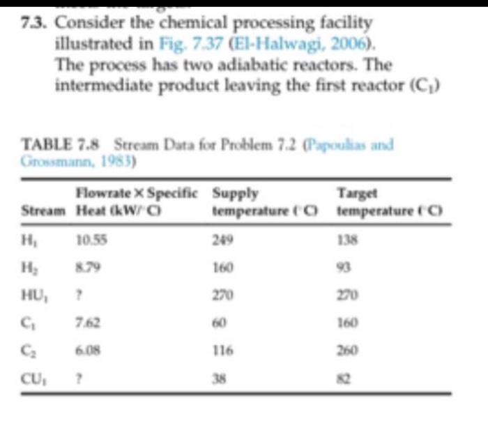
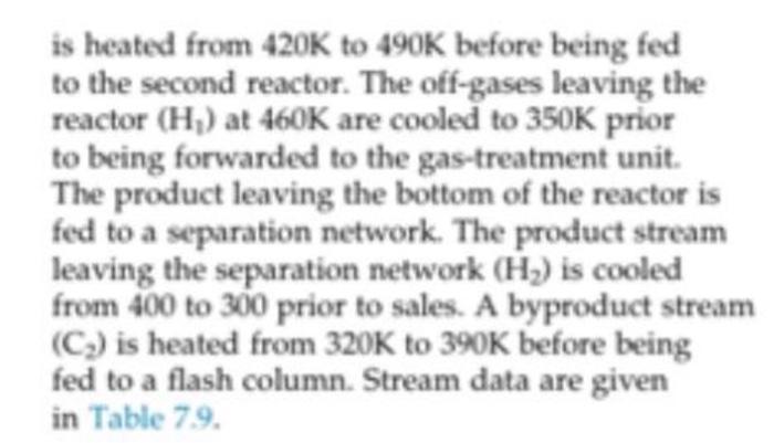
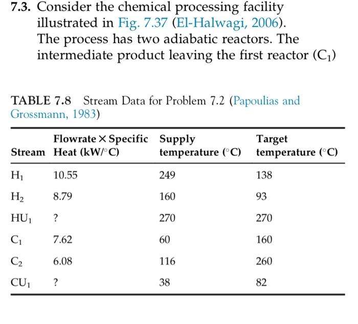
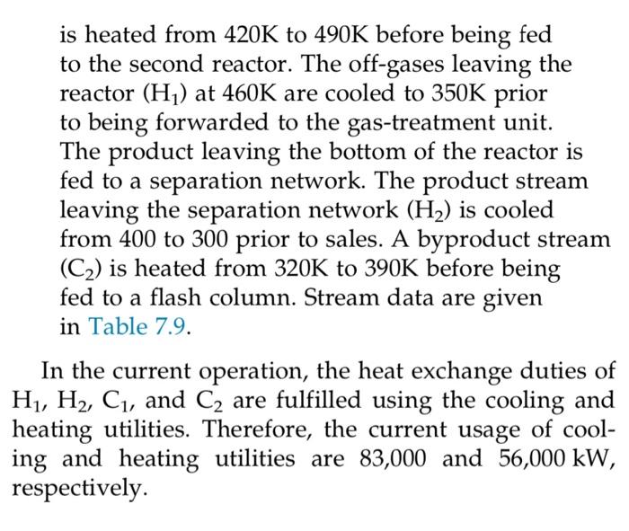
7.3. Consider the chemical processing facility illustrated in Fig. 7.37 (El-Halwagi, 2006). The process has two adiabatic reactors. The intermediate product leaving the first reactor (C) TABLE 7.8 Stream Data for Problem 7.2 (Papoulias and Grossmann, 1983) Flowrate X Specific Supply Target Stream Heat (kW/O temperature (o temperature (C) H 10.55 249 138 160 HU, 270 7.62 60 160 6.08 116 250 CU, 2 38 is heated from 420K to 490K before being fed to the second reactor. The off-gases leaving the reactor (H) at 460K are cooled to 350K prior to being forwarded to the gas-treatment unit. The product leaving the bottom of the reactor is fed to a separation network. The product stream leaving the separation network (H) is cooled from 400 to 300 prior to sales. A byproduct stream (C) is heated from 320K to 390K before being fed to a flash column. Stream data are given in Table 79. In the current operation, the heat exchange duties of H, H, C. and C are fulfilled using the cooling and heating utilities. Therefore, the current usage of cool- ing and heating utilities are 83,000 and 56,000 kW, respectively. The objective of this problem is to identify the target for minimum heating and cooling utilities and to syn- thesize a network of heat exchangers that achieves the utility targets. A value of ATmin= 10K is used. 7.3. Consider the chemical processing facility illustrated in Fig. 7.37 (El-Halwagi, 2006). The process has two adiabatic reactors. The intermediate product leaving the first reactor (C1) TABLE 7.8 Stream Data for Problem 7.2 (Papoulias and Grossmann, 1983) Flowrate X Specific Supply Stream Heat (kW/C) temperature (C) Target temperature (C) H 10.55 249 138 H2 8.79 160 93 HU, ? 270 270 7.62 60 160 C2 6.08 116 260 CU ? 38 82 is heated from 420K to 490K before being fed to the second reactor. The off-gases leaving the reactor (H) at 460K are cooled to 350K prior to being forwarded to the gas-treatment unit. The product leaving the bottom of the reactor is fed to a separation network. The product stream leaving the separation network (H2) is cooled from 400 to 300 prior to sales. A byproduct stream (C2) is heated from 320K to 390K before being fed to a flash column. Stream data are given a in Table 7.9. In the current operation, the heat exchange duties of H1, H2, C1, and C2 are fulfilled using the cooling and heating utilities. Therefore, the current usage of cool- ing and heating utilities are 83,000 and 56,000 kW, respectively. The objective of this problem is to identify the target for minimum heating and cooling utilities and to syn- thesize a network of heat exchangers that achieves the utility targets. A value of Armin = 10K is used
