Answered step by step
Verified Expert Solution
Question
1 Approved Answer
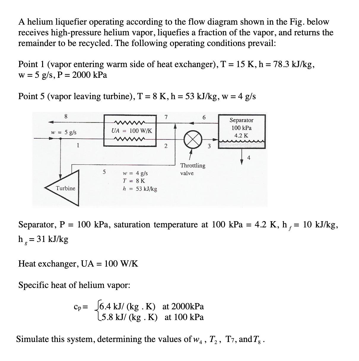
helium liquefier operating according to the flow diagram shown in the Fig. below receives high-pressure helium vapor, liquefies a fraction of the vapor, and

helium liquefier operating according to the flow diagram shown in the Fig. below receives high-pressure helium vapor, liquefies a fraction of the vapor, and returns the remainder to be recycled. The following operating conditions prevail: Point 1 (vapor entering warm side of heat exchanger), T = 15 K, h = 78.3 kJ/kg, w = 5 g/s, P = 2000 kPa Point 5 (vapor leaving turbine), T = 8 K, h = 53 kJ/kg, w = 4 g/s 8 5 g/s w = 5 Turbine 1 5 UA= 100 W/K w = 4 g/s T = 8 K h = 53 kJ/kg 7 Heat exchanger, UA = 100 W/K Specific heat of helium vapor: Cp= 2 A 6 Throttling valve 3 Separator 100 kPa 4.2 K 4 Separator, P = 100 kPa, saturation temperature at 100 kPa = 4.2 K, h : = 10 kJ/kg, h = 31 kJ/kg 6.4 kJ/ (kg . K) at 2000kPa 5.8 kJ/ (kg. K) at 100 kPa Simulate this system, determining the values of w, T, T7, and Tg.
Step by Step Solution
★★★★★
3.38 Rating (176 Votes )
There are 3 Steps involved in it
Step: 1
Solutions Vapor entering warm side of heat exchanger T 15k h 783kJkg 5 gs and P 2000 Kpa v...
Get Instant Access to Expert-Tailored Solutions
See step-by-step solutions with expert insights and AI powered tools for academic success
Step: 2

Step: 3

Ace Your Homework with AI
Get the answers you need in no time with our AI-driven, step-by-step assistance
Get Started


