Answered step by step
Verified Expert Solution
Question
1 Approved Answer
Hello, I would very much appreciate it if you can answer question 5 and 6 please. Assignment 2.1 - Design for Control Controlling the movement


Hello, I would very much appreciate it if you can answer question 5 and 6 please.
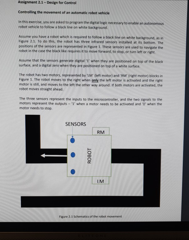
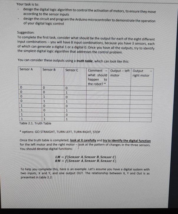
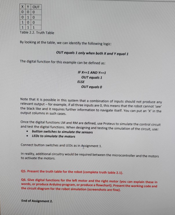
Assignment 2.1 - Design for Control Controlling the movement of an automatic robot vehicle In this exercise, you are asked to program the digital logic necessary to enable an autonomous robot vehicle to follow a black line on white background. Assume you have a robot which is required to follow a black line on white background, as in Figure 2.1. To do this, the robot has three infrared sensors installed at its bottom. The positions of the sensors are represented in Figure 1. These sensors are used to navigate the robot in the case the black like requires it to move forward, to stop, or turn left or right. Assume that the sensors generate digital '1' when they are positioned on top of the black surface, and a digital zero when they are positioned on top of a white surface. The robot has two motors, represented by 'LM' (left motor) and 'RM' (right motor) blocks in Figure 1. The robot moves to the right when only the left motor is activated and the right motor is still, and moves to the left the other way around. If both motors are activated, the robot moves straight ahead. The three sensors represent the inputs to the microcontroller, and the two signals to the motors represent the outputs - '1' when a motor needs to be activated and 'o' when the motor needs to stop SENSORS RM ROBOT LM Figure 2.1 Schematics of the robot movement Your task is to: design the digital logic algorithm to control the activation of motors, to ensure they move according to the sensor inputs design the circuit and program the Arduino microcontroller to demonstrate the operation of your digital logic control Suggestion: To complete the first task, consider what should be the output for each of the eight different input combinations - you will have 8 input combinations, because you have 3 sensors, each of which can generate a digital 1 or a digital o. Once you have all the outputs, try to identify the simplest digital logic algorithm that addresses the control problem. You can consider these outputs using a truth table, which can look like this: Sensor A Sensor B Sensor C Comment - Output - left Output - what should motor right motor happen to the robot? Table 2.1. Truth Table * options: GO STRAIGHT, TURN LEFT, TURN RIGHT, STOP Once the truth table is completed, look at it carefully and try to identify the digital function for the left motor and the right motor - look at the pattern of changes in the three sensors. You should develop digital functions: LM = f(Sensor A, Sensor B, Sensor C} RM = f(Sensor A, Sensor B, Sensor C To help you complete this, here is an example. Let's assume you have a digital system with two inputs, X and Y, and one output OUT. The relationship between X Y and Out is as presented in table 2.2: XY OUT 000 100 1 1 1 Table 2.2. Truth Table By looking at the table, we can identify the following logic OUT equals 1 only when both X and Y equal 1 The digital function for this example can be defined as: IF X==1 AND Y==1 OUT equals 1 ELSE OUT equals o Note that it is possible in this system that a combination of inputs should not produce any relevant output--for example, if all three inputs are 0, this means that the robot cannot see the black like and it requires further information to navigate itself. You can put an "Xin the output columns in such cases. Once the digital functions LM and RM are defined, use Proteus to simulate the control Circuit and test the digital functions. When designing and testing the simulation of the circuit, use: button switches to simulate the sensors LEDs to simulate the motors Connect button switches and LEDs as in Assignment 1. In reality, additional circuitry would be required between the microcontroller and the motors to activate the motors. Q5. Present the truth table for the robot (complete truth table 2.1). Q6. Give digital functions for the left motor and the right motor (you can explain these in words, or produce Arduino program, or produce a flowchart). Present the working code and the circuit diagram for the robot simulation (screenshots are fine) End of Assignment 2Step by Step Solution
There are 3 Steps involved in it
Step: 1

Get Instant Access to Expert-Tailored Solutions
See step-by-step solutions with expert insights and AI powered tools for academic success
Step: 2

Step: 3

Ace Your Homework with AI
Get the answers you need in no time with our AI-driven, step-by-step assistance
Get Started


