Question: Hello I'm trying to write a report after collecting this data about conservation of energy and momentum. Please any help would be much appreciated Data
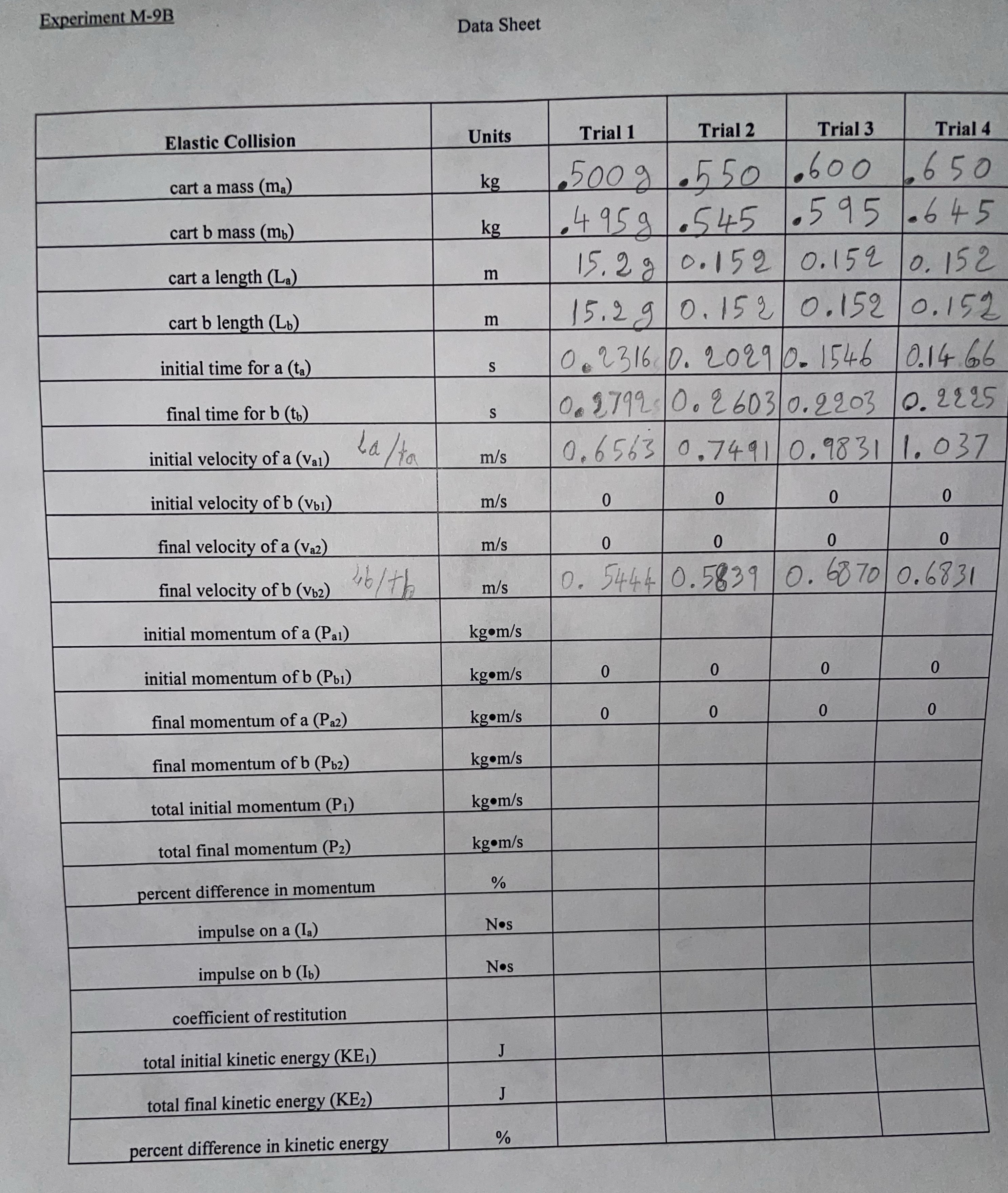
Hello I'm trying to write a report after collecting this data about conservation of energy and momentum. Please any help would be much appreciated
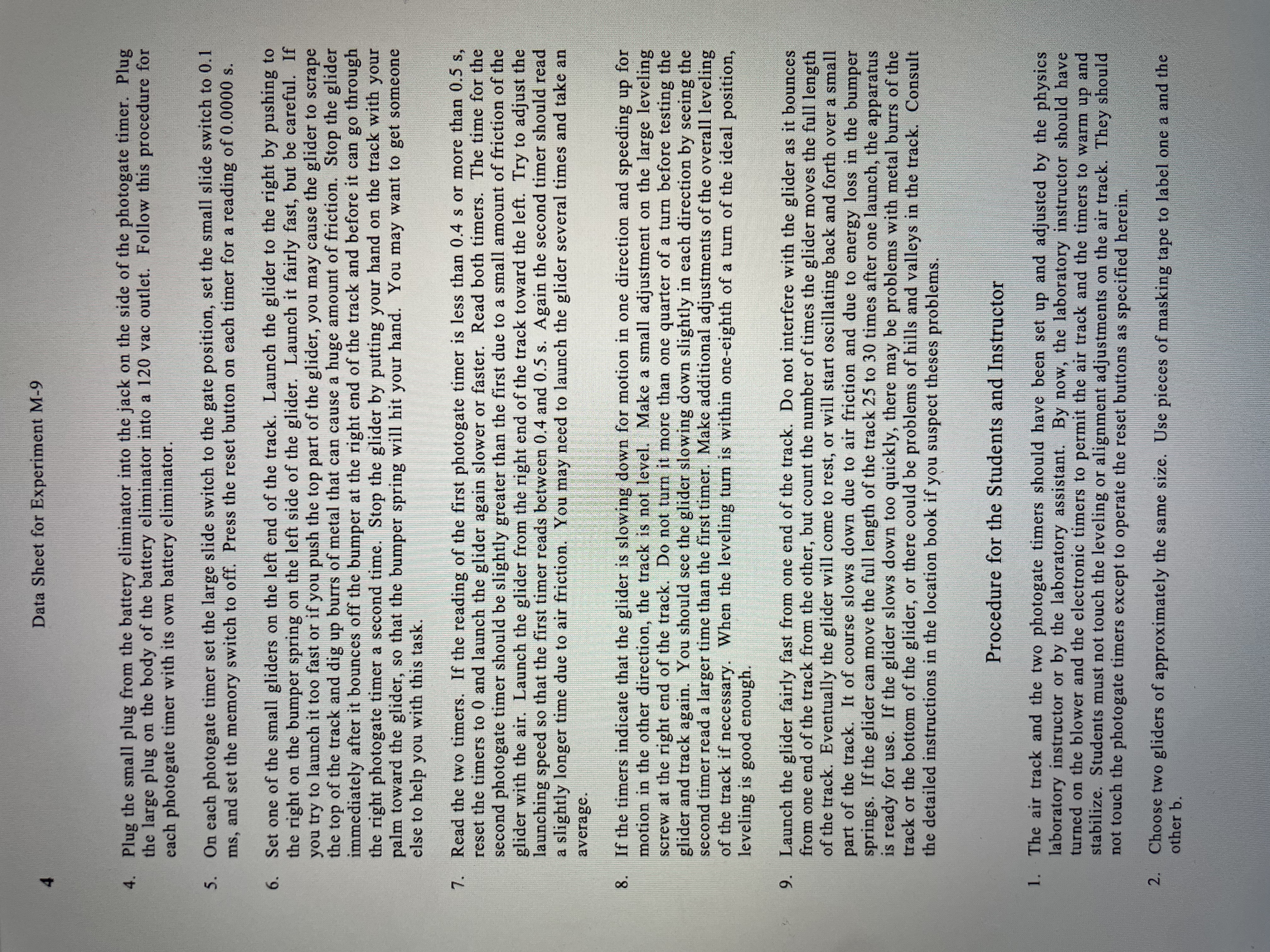
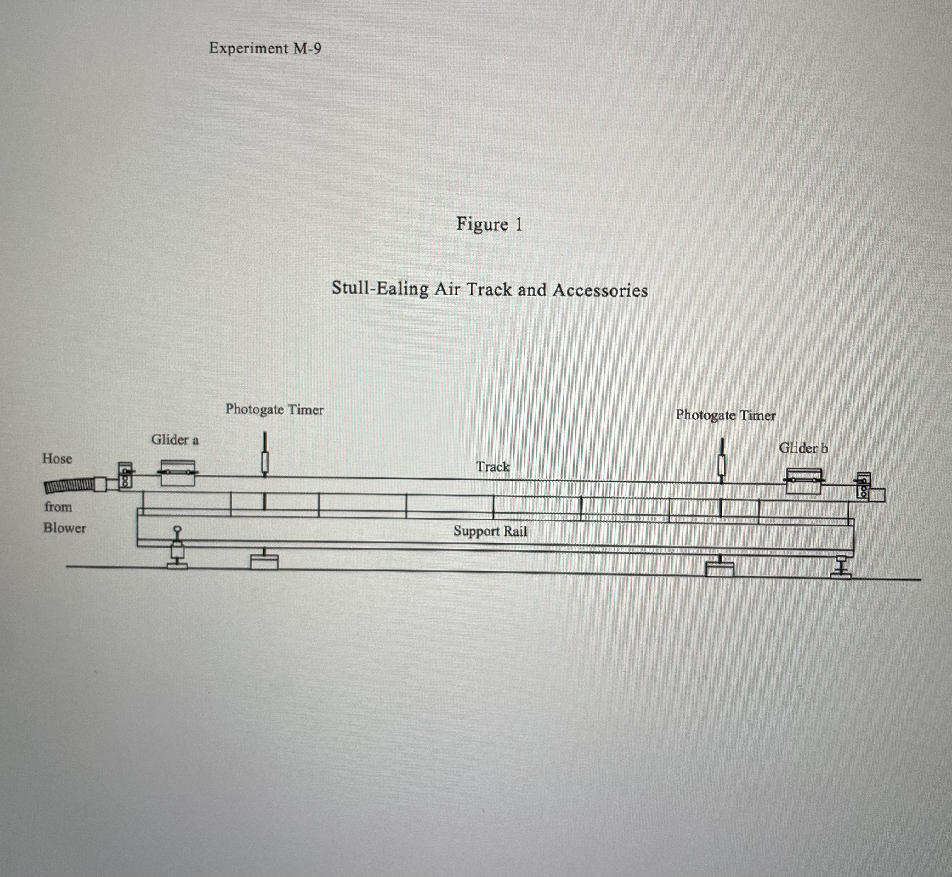
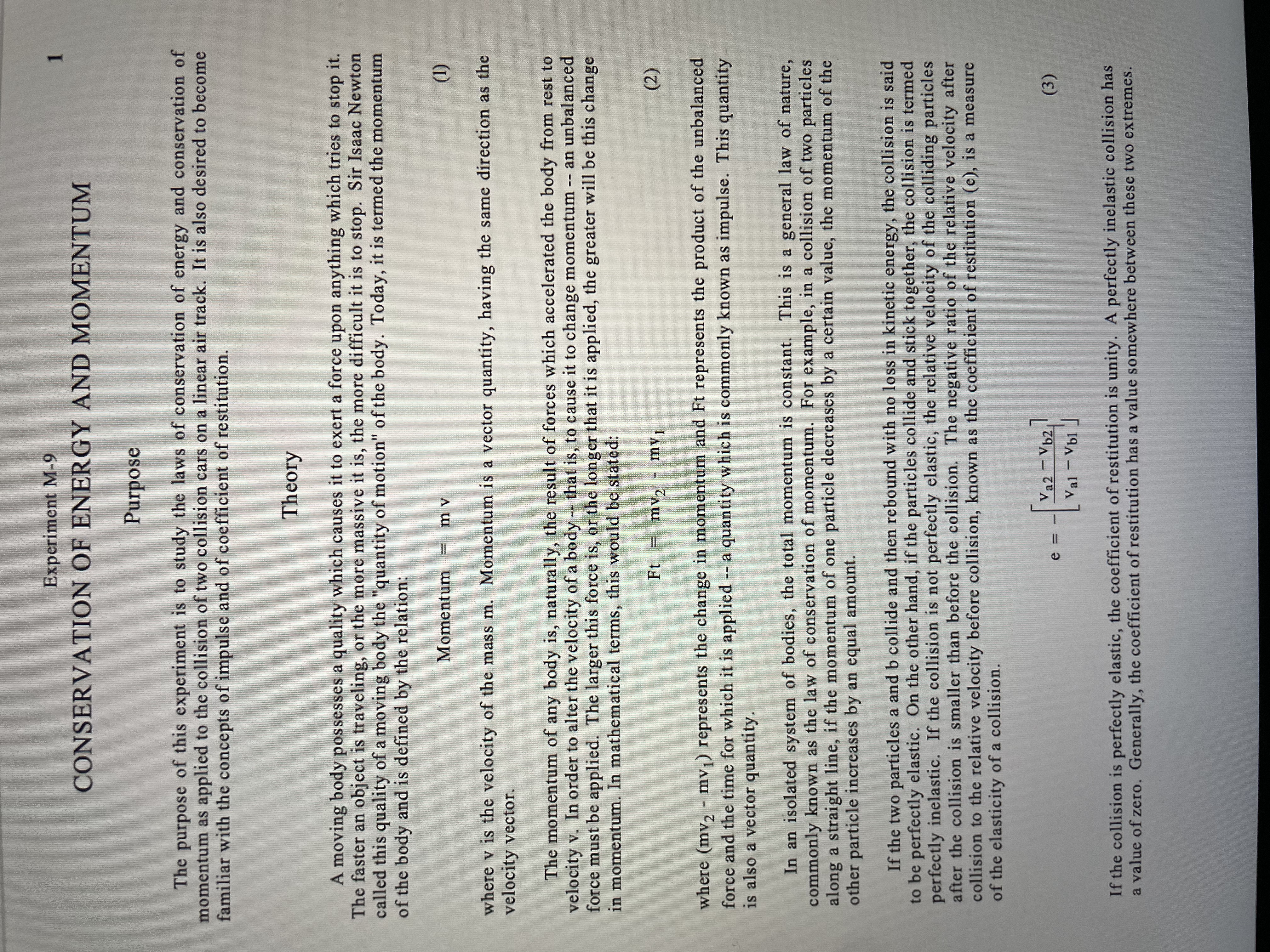
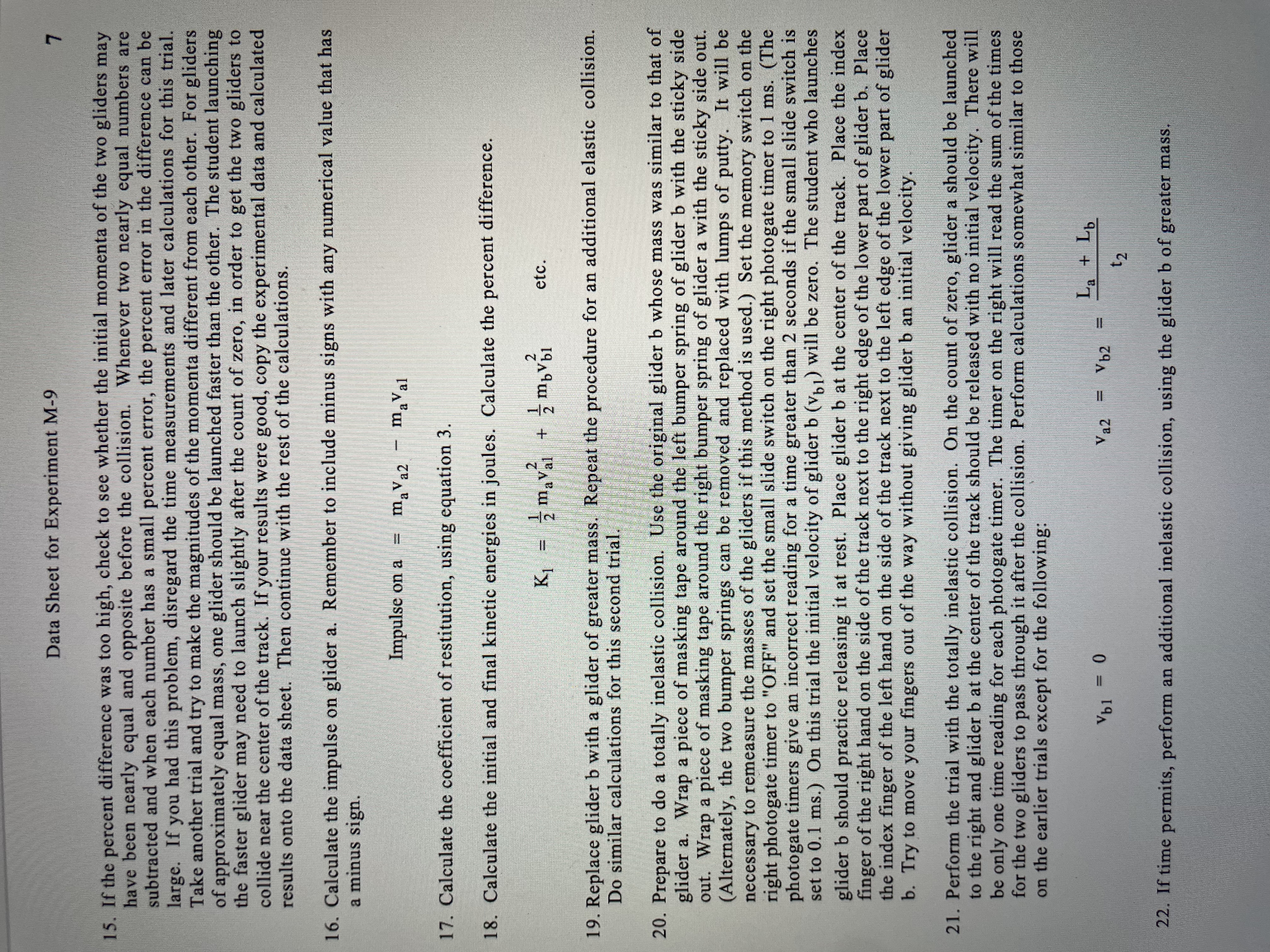
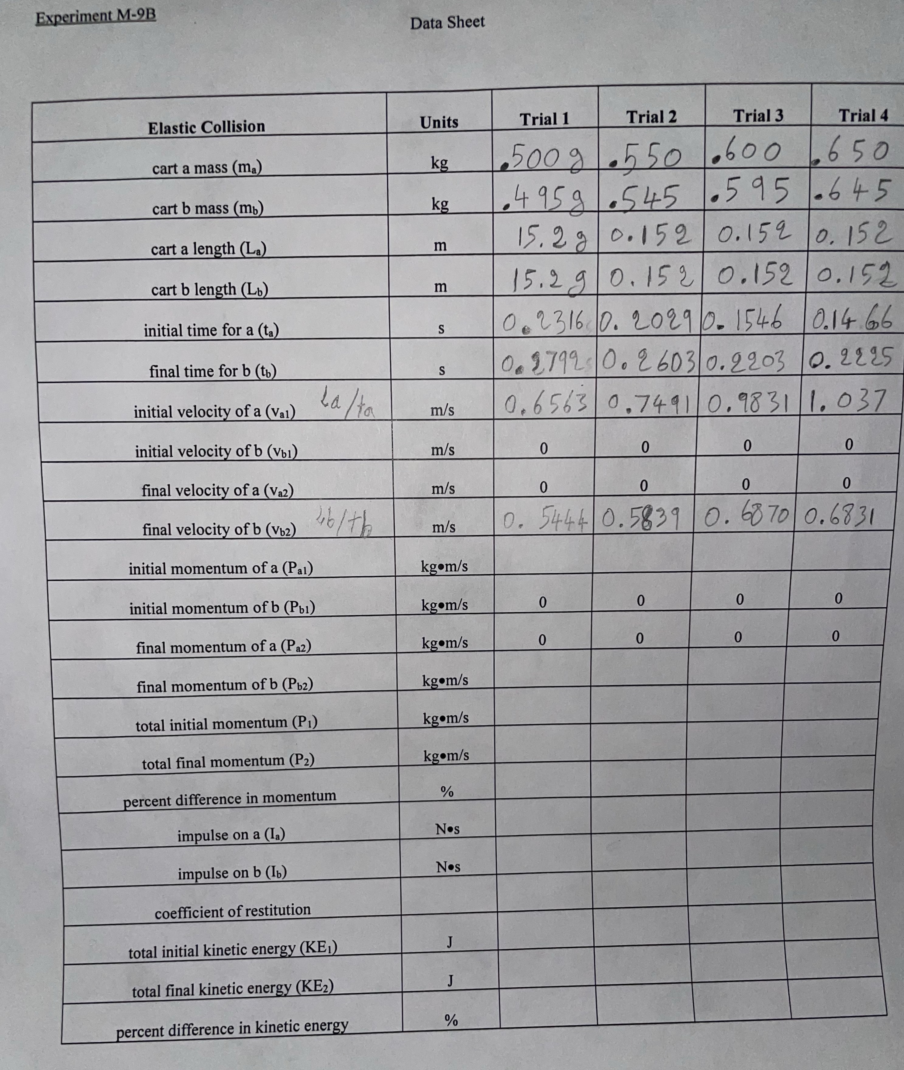
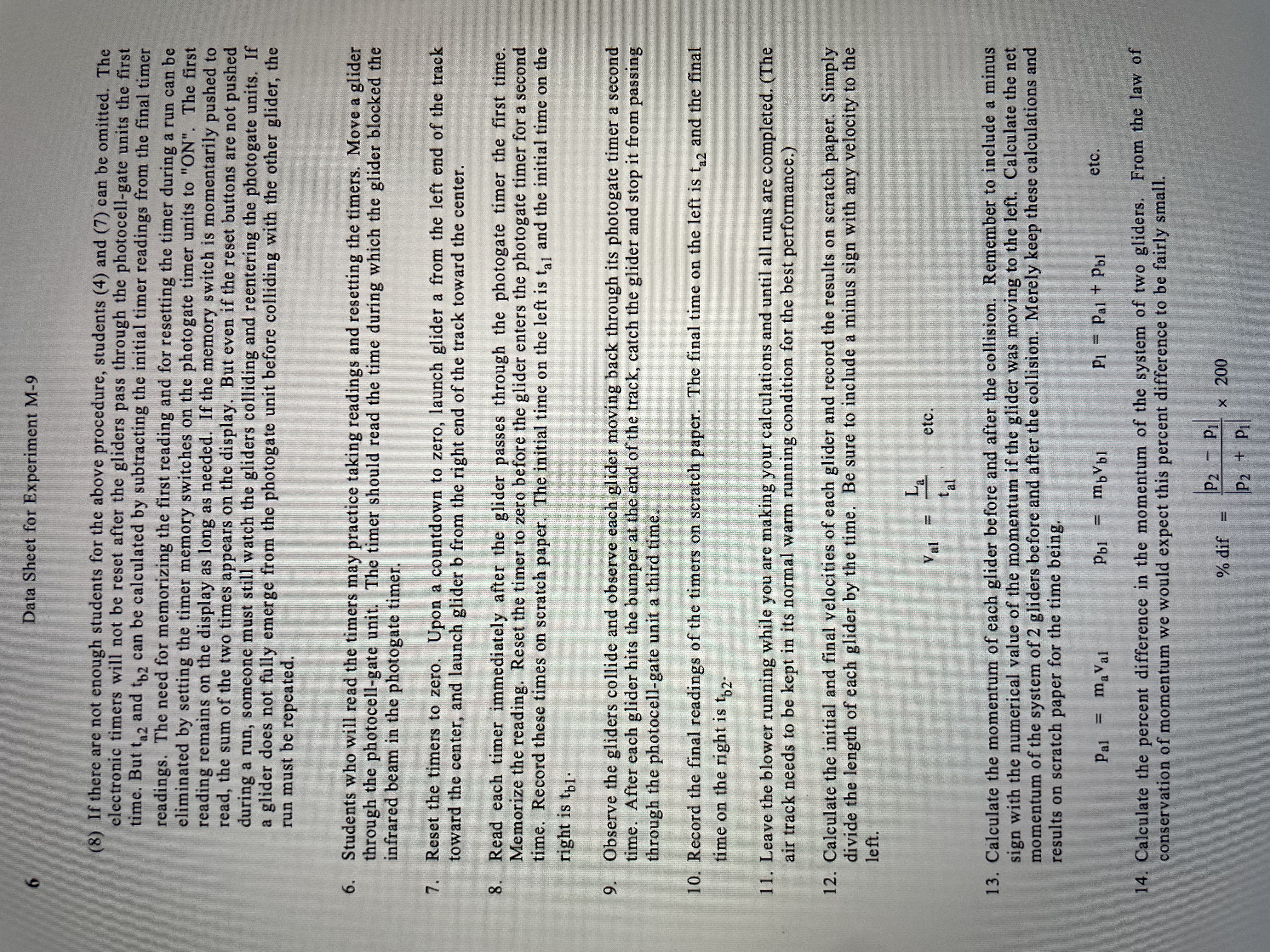
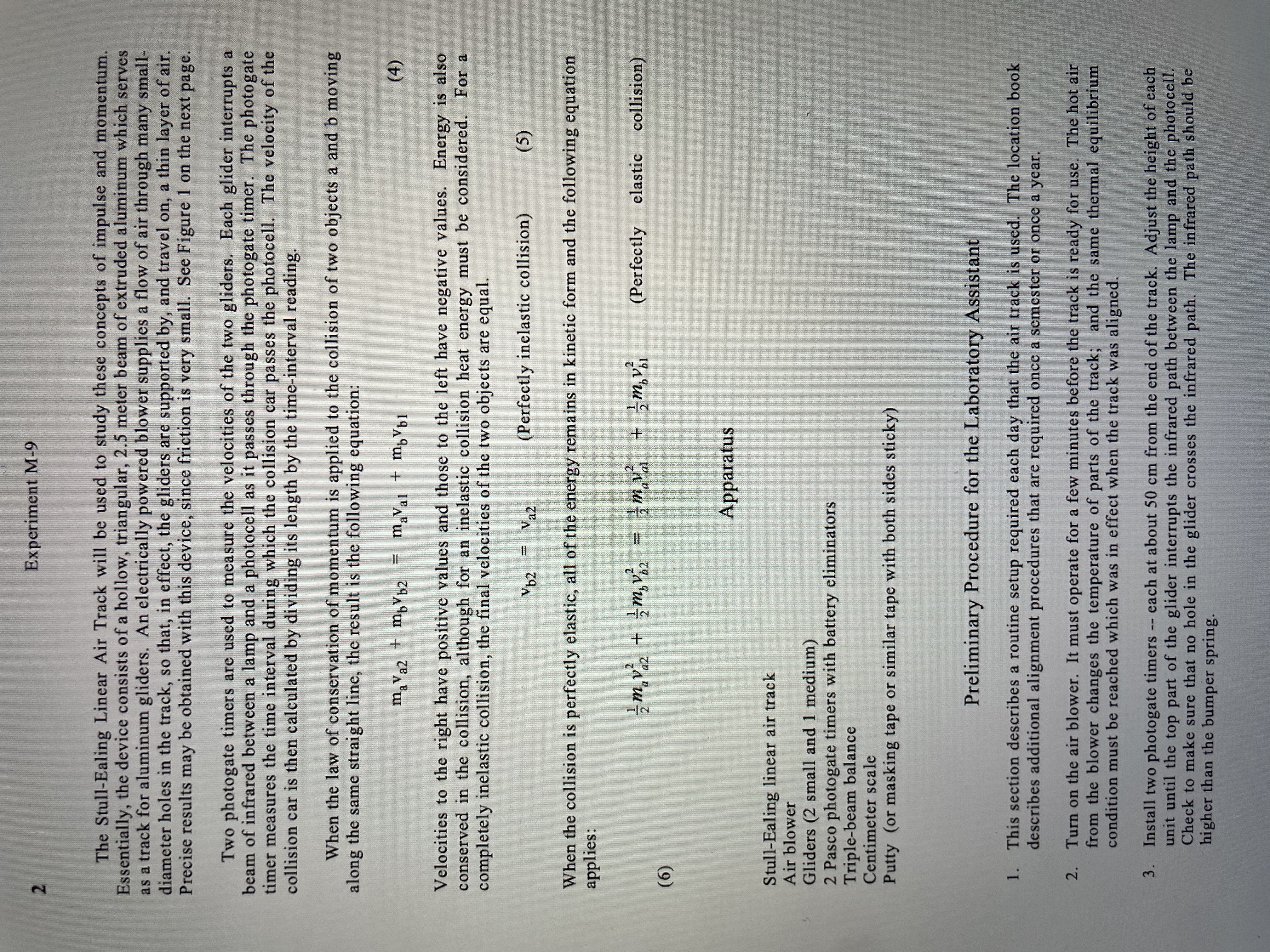
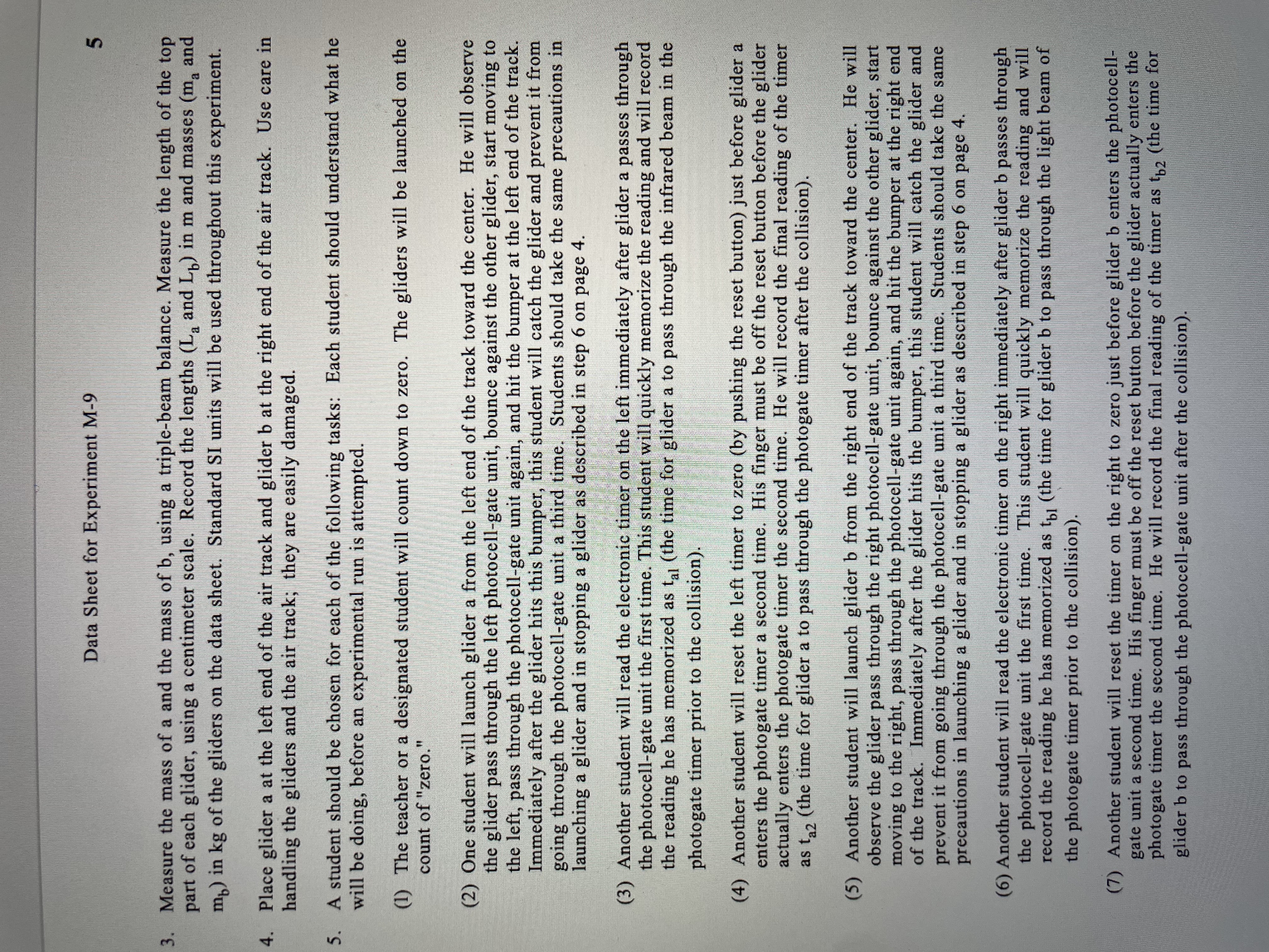
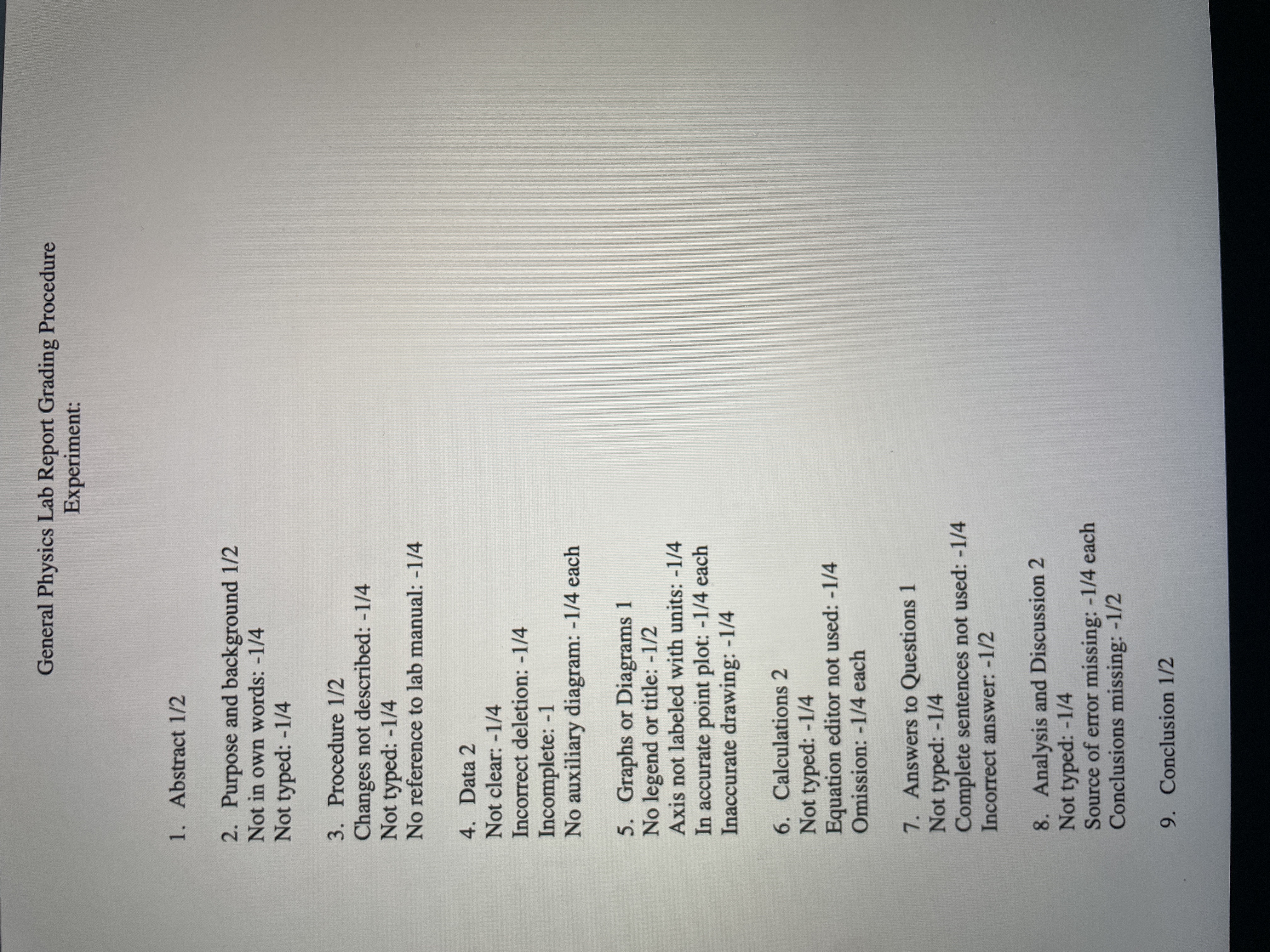
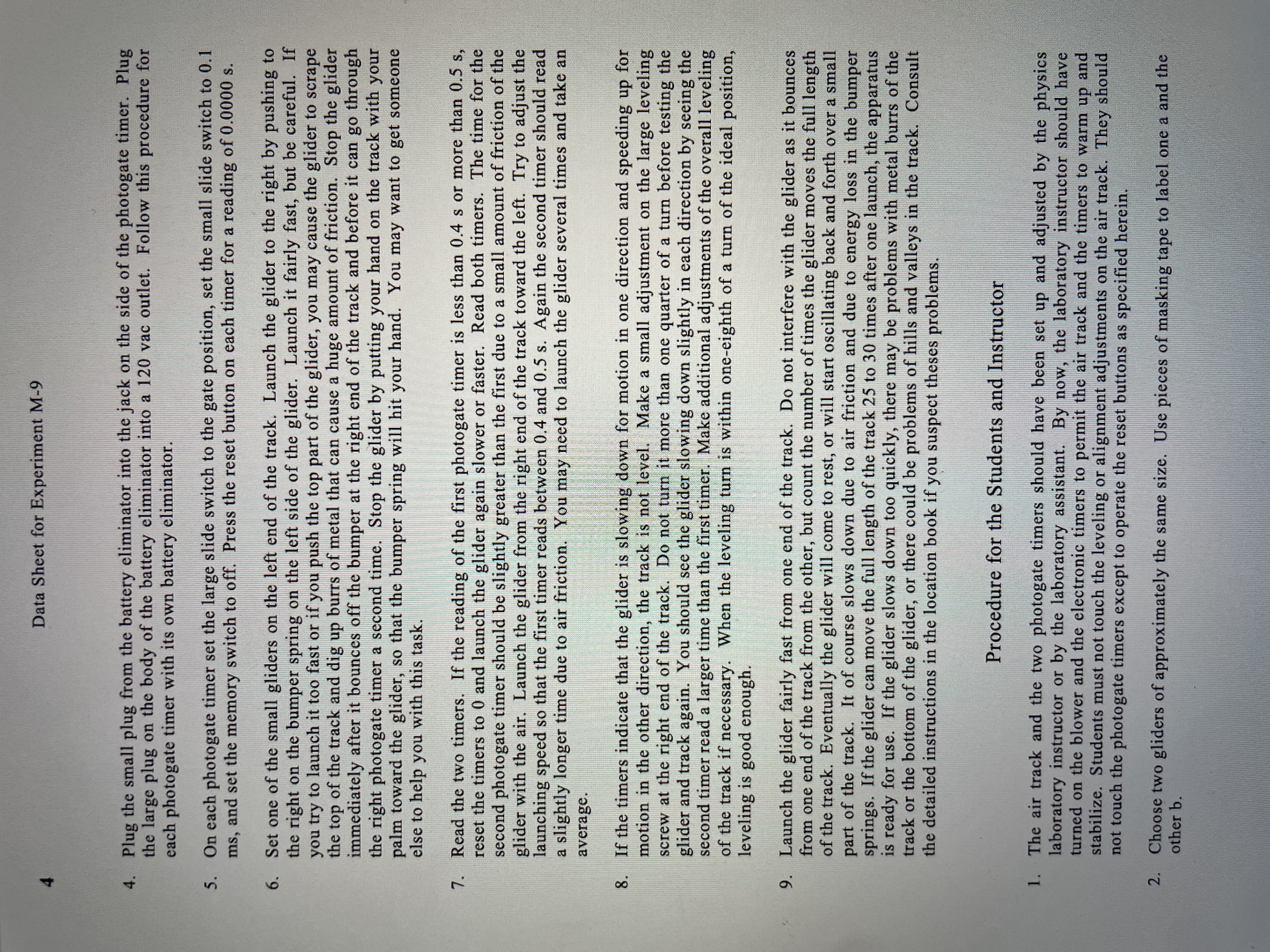
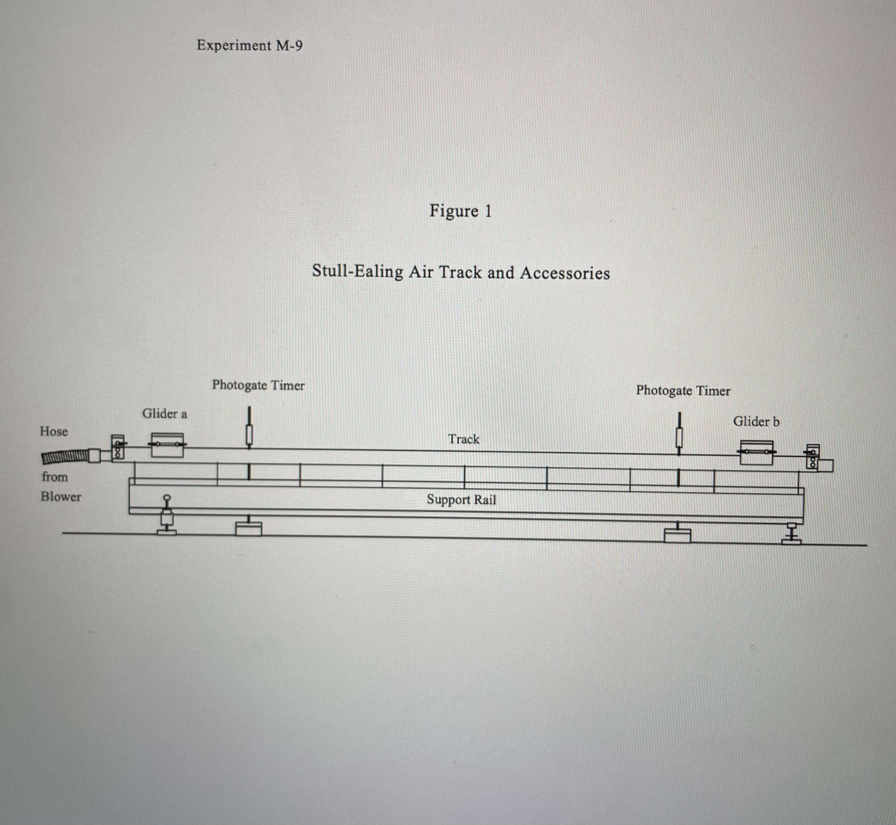
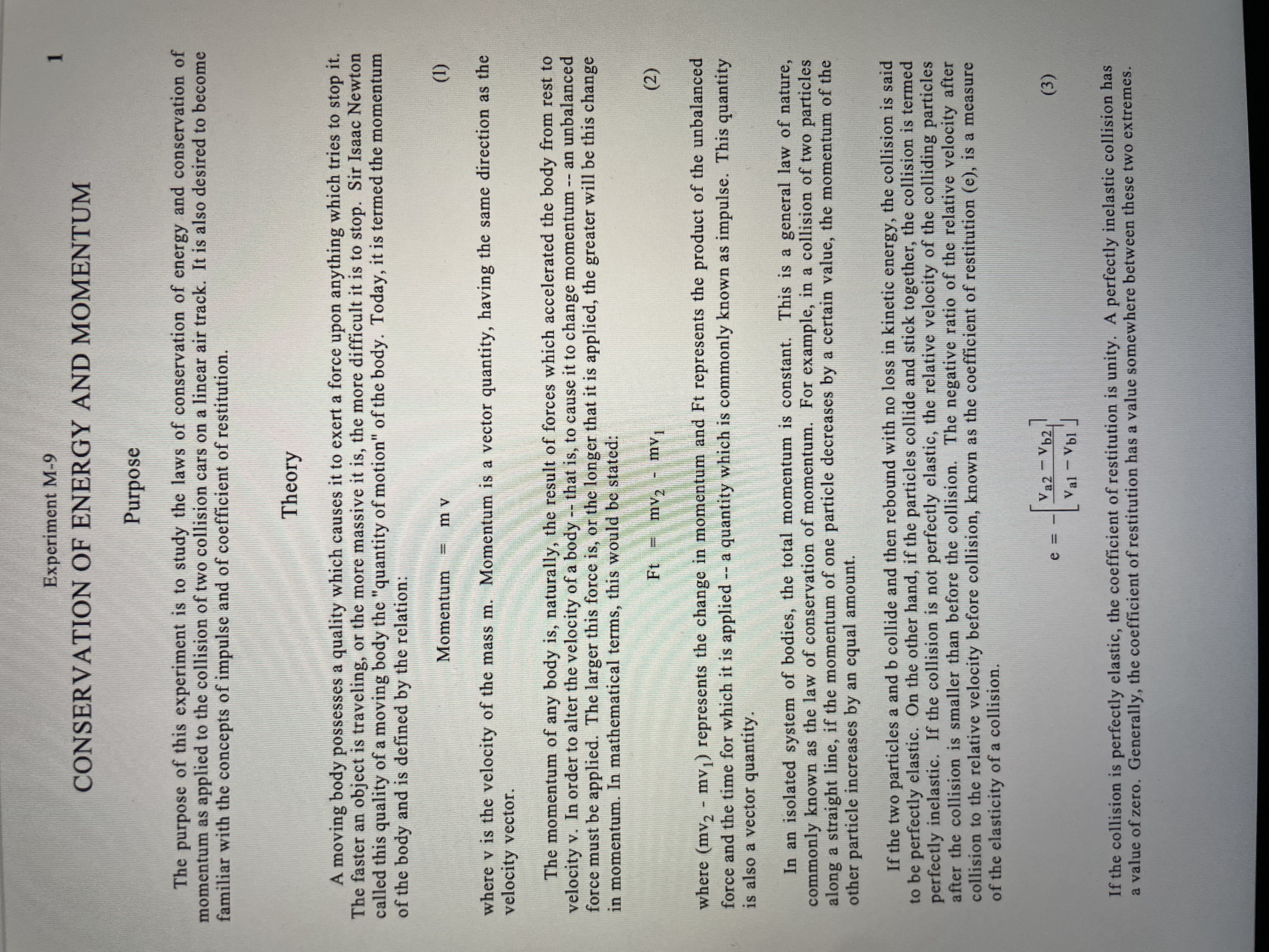
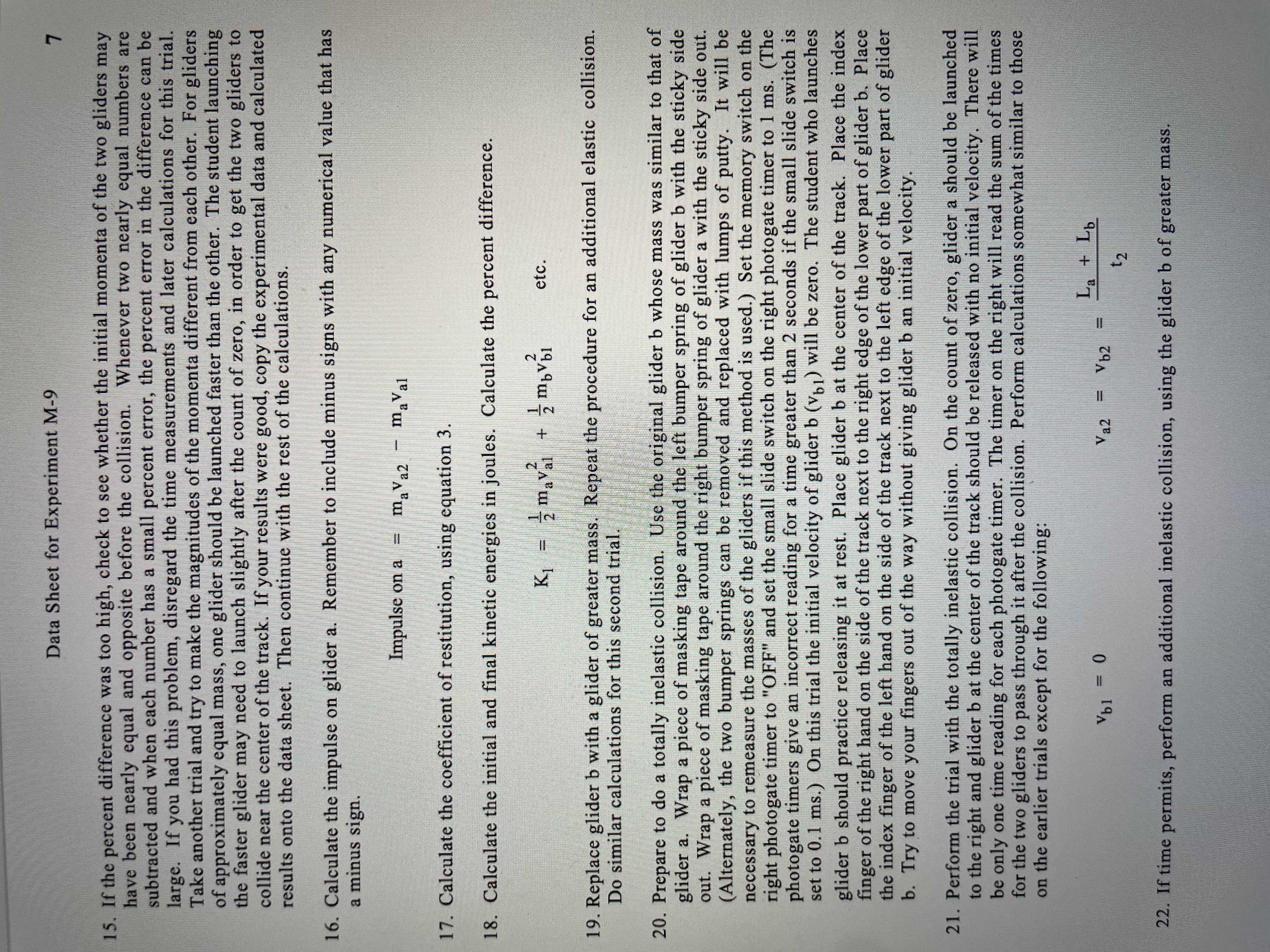
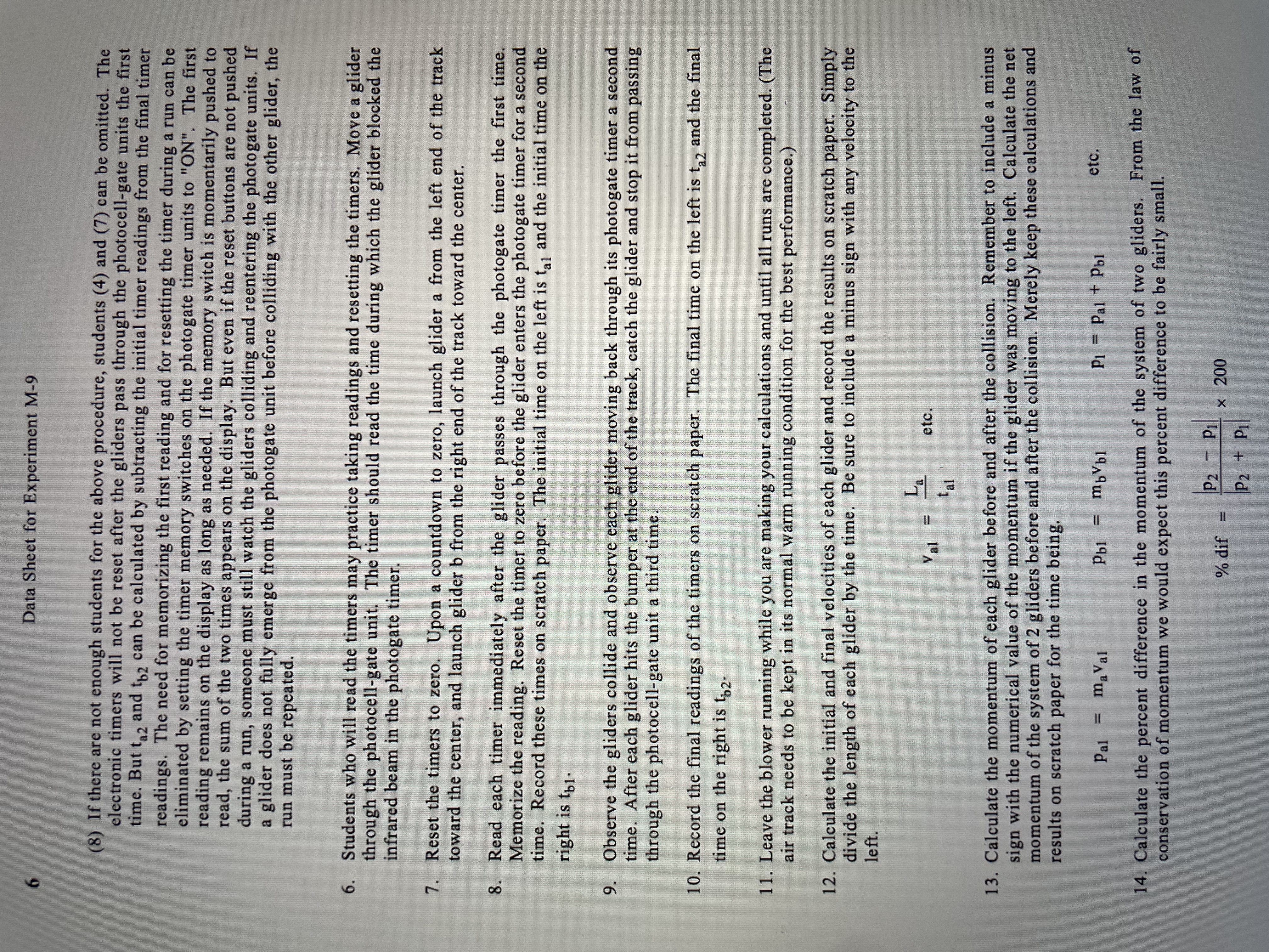
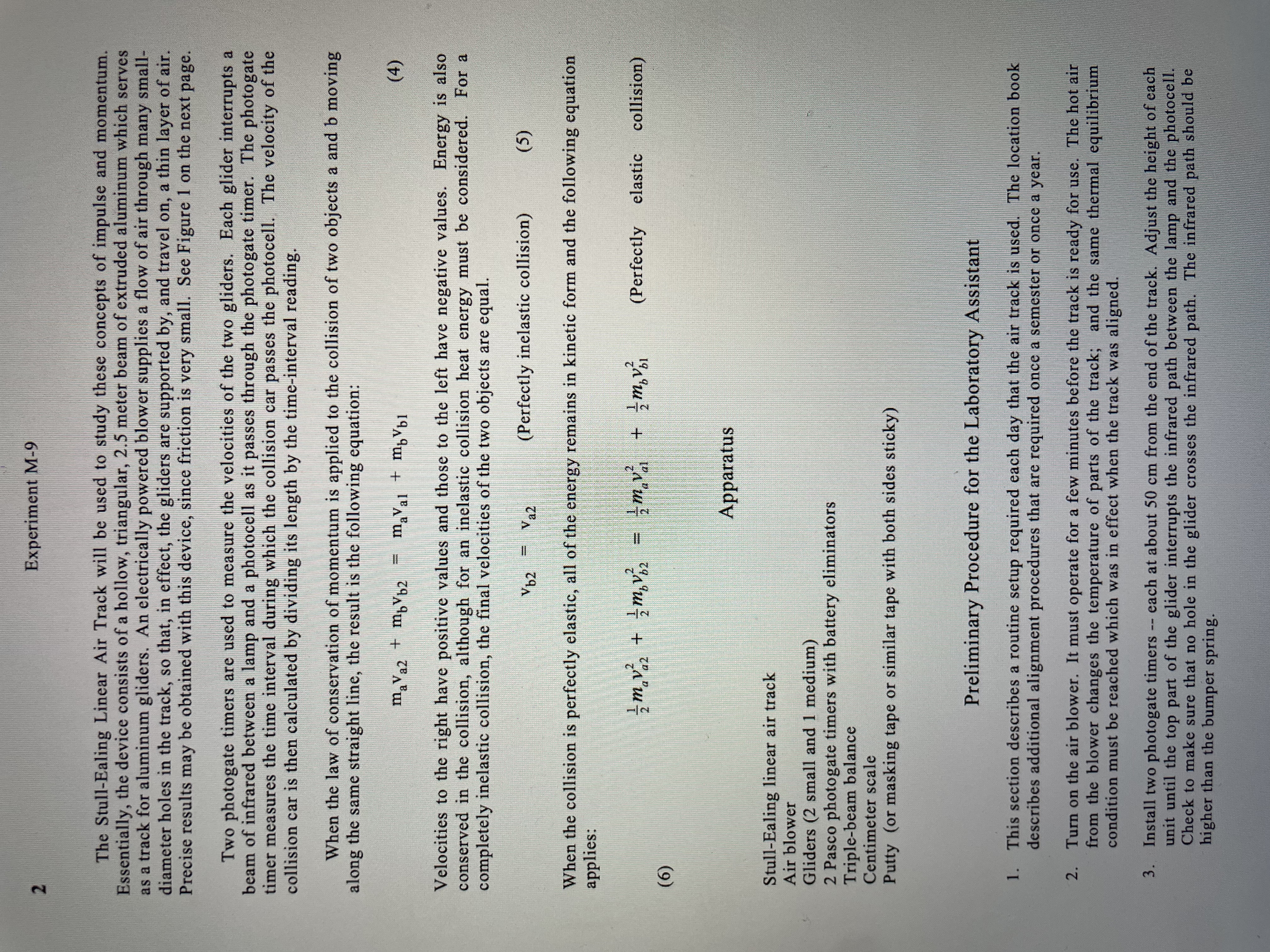
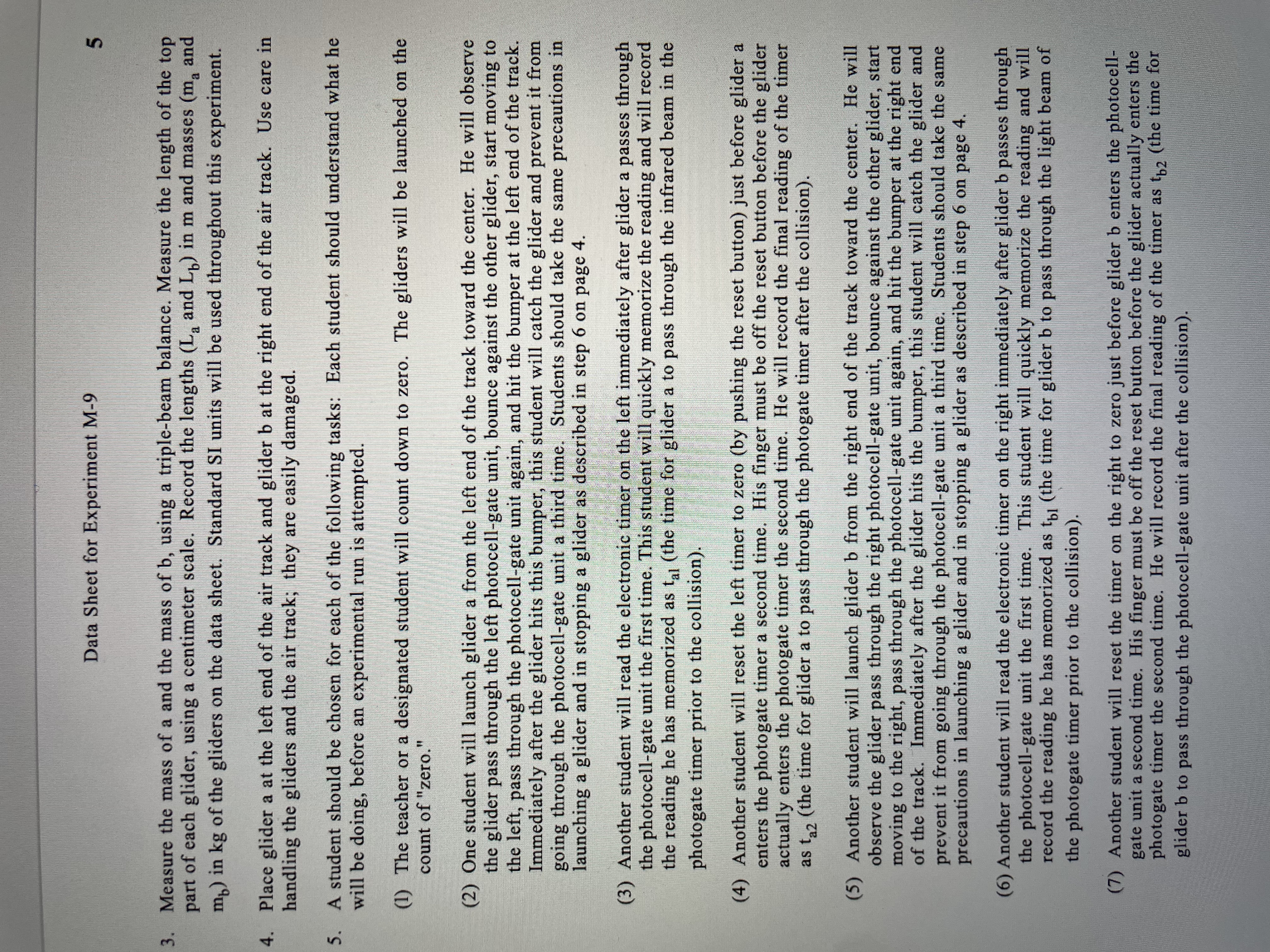
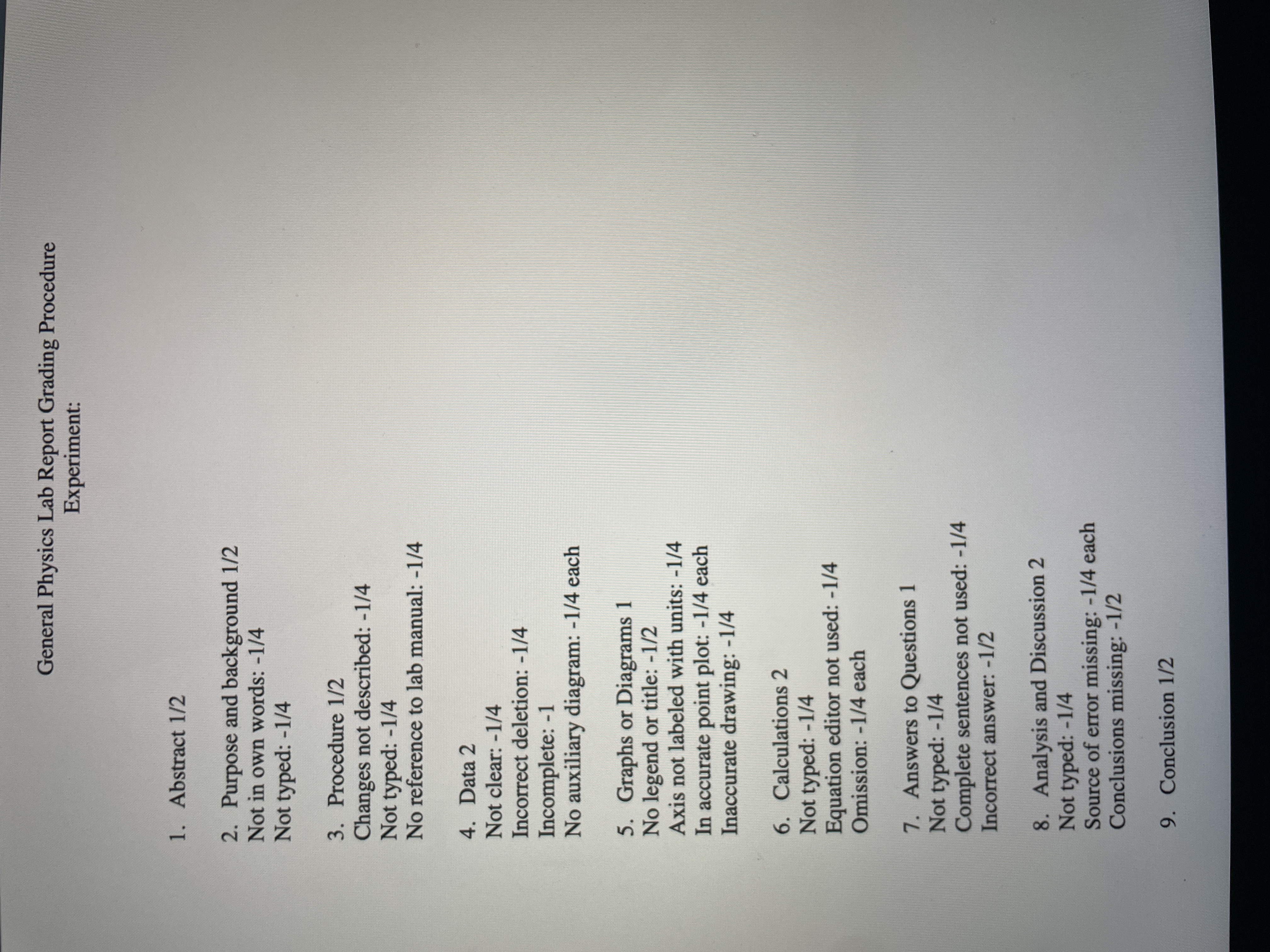
Data Sheet for Experiment M-9 4. Plug the small plug from the battery eliminator into the jack on the side of the photogate timer. Plug the large plug on the body of the battery eliminator into a 120 vac outlet. Follow this procedure for each photogate timer with its own battery eliminator. 5. On each photogate timer set the large slide switch to the gate position, set the small slide switch to 0.1 ms, and set the memory switch to off. Press the reset button on each timer for a reading of 0.0000 s. 6. Set one of the small gliders on the left end of the track. Launch the glider to the right by pushing to the right on the bumper spring on the left side of the glider. Launch it fairly fast, but be careful. If you try to launch it too fast or if you push the top part of the glider, you may cause the glider to scrape the top of the track and dig up burrs of metal that can cause a huge amount of friction. Stop the glider immediately after it bounces off the bumper at the right end of the track and before it can go through the right photogate timer a second time. Stop the glider by putting your hand on the track with your palm toward the glider, so that the bumper spring will hit your hand. You may want to get someone else to help you with this task. 7. Read the two timers. If the reading of the first photogate timer is less than 0.4 s or more than 0.5 s, reset the timers to 0 and launch the glider again slower or faster. Read both timers. The time for the second photogate timer should be slightly greater than the first due to a small amount of friction of the glider with the air. Launch the glider from the right end of the track toward the left. Try to adjust the launching speed so that the first timer reads between 0.4 and 0.5 s. Again the second timer should read a slightly longer time due to air friction. You may need to launch the glider several times and take an average. If the timers indicate that the glider is slowing down for motion in one direction and speeding up for motion in the other direction, the track is not level. Make a small adjustment on the large leveling screw at the right end of the track. Do not turn it more than one quarter of a turn before testing the glider and track again. You should see the glider slowing down slightly in each direction by seeing the second timer read a larger time than the first timer. Make additional adjustments of the overall leveling of the track if necessary. When the leveling turn is within one-eighth of a turn of the ideal position, leveling is good enough. 9. Launch the glider fairly fast from one end of the track. Do not interfere with the glider as it bounces from one end of the track from the other, but count the number of times the glider moves the full length of the track. Eventually the glider will come to rest, or will start oscillating back and forth over a small part of the track. It of course slows down due to air friction and due to energy loss in the bumper springs. If the glider can move the full length of the track 25 to 30 times after one launch, the apparatus is ready for use. If the glider slows down too quickly, there may be problems with metal burrs of the track or the bottom of the glider, or there could be problems of hills and valleys in the track. Consult the detailed instructions in the location book if you suspect theses problems. Procedure for the Students and Instructor 1. The air track and the two photogate timers should have been set up and adjusted by the physics laboratory instructor or by the laboratory assistant. By now, the laboratory instructor should have turned on the blower and the electronic timers to permit the air track and the timers to warm up and stabilize. Students must not touch the leveling or alignment adjustments on the air track. They should not touch the photogate timers except to operate the reset buttons as specified herein. 2. Choose two gliders of approximately the same size. Use pieces of masking tape to label one a and the other b.Experiment M-9 Figure 1 Stull-Ealing Air Track and Accessories Photogate Timer Photogate Timer Glider a Glider b Hose Track from Blower Support RailExperiment M-9 CONSERVATION OF ENERGY AND MOMENTUM Purpose The purpose of this experiment is to study the laws of conservation of energy and conservation of momentum as applied to the collision of two collision cars on a linear air track. It is also desired to become familiar with the concepts of impulse and of coefficient of restitution. Theory A moving body possesses a quality which causes it to exert a force upon anything which tries to stop it. The faster an object is traveling, or the more massive it is, the more difficult it is to stop. Sir Isaac Newton called this quality of a moving body the "quantity of motion" of the body. Today, it is termed the momentum of the body and is defined by the relation: Momentum m v (1) where v is the velocity of the mass m. Momentum is a vector quantity, having the same direction as the velocity vector. The momentum of any body is, naturally, the result of forces which accelerated the body from rest to velocity v. In order to alter the velocity of a body -- that is, to cause it to change momentum -- an unbalanced force must be applied. The larger this force is, or the longer that it is applied, the greater will be this change in momentum. In mathematical terms, this would be stated: Ft my2 mv 1 (2) where (mv2 - mv1) represents the change in momentum and Ft represents the product of the unbalanced force and the time for which it is applied -- a quantity which is commonly known as impulse. This quantity is also a vector quantity. In an isolated system of bodies, the total momentum is constant. This is a general law of nature, commonly known as the law of conservation of momentum. For example, in a collision of two particles along a straight line, if the momentum of one particle decreases by a certain value, the momentum of the other particle increases by an equal amount. If the two particles a and b collide and then rebound with no loss in kinetic energy, the collision is said to be perfectly elastic. On the other hand, if the particles collide and stick together, the collision is termed perfectly inelastic. If the collision is not perfectly elastic, the relative velocity of the colliding particles after the collision is smaller than before the collision. The negative ratio of the relative velocity after collision to the relative velocity before collision, known as the coefficient of restitution (e), is a measure of the elasticity of a collision. e = -Va2 - Vb21 (3 ) Val - vbill If the collision is perfectly elastic, the coefficient of restitution is unity. A perfectly inelastic collision has a value of zero. Generally, the coefficient of restitution has a value somewhere between these two extremes.Data Sheet for Experiment M-9 7 15. If the percent difference was too high, check to see whether the initial momenta of the two gliders may have been nearly equal and opposite before the collision. Whenever two nearly equal numbers are subtracted and when each number has a small percent error, the percent error in the difference can be large. If you had this problem, disregard the time measurements and later calculations for this trial. Take another trial and try to make the magnitudes of the momenta different from each other. For gliders of approximately equal mass, one glider should be launched faster than the other. The student launching the faster glider may need to launch slightly after the count of zero, in order to get the two gliders to collide near the center of the track. If your results were good, copy the experimental data and calculated results onto the data sheet. Then continue with the rest of the calculations. 16. Calculate the impulse on glider a. Remember to include minus signs with any numerical value that has a minus sign. Impulse on a = maVa2 maVal 17. Calculate the coefficient of restitution, using equation 3. 18. Calculate the initial and final kinetic energies in joules. Calculate the percent difference. K1 = 2 maVal z movbl etc. 19. Replace glider b with a glider of greater mass. Repeat the procedure for an additional elastic collision. Do similar calculations for this second trial. 20. Prepare to do a totally inelastic collision. Use the original glider b whose mass was similar to that of glider a. Wrap a piece of masking tape around the left bumper spring of glider b with the sticky side out. Wrap a piece of masking tape around the right bumper spring of glider a with the sticky side out. (Alternately, the two bumper springs can be removed and replaced with lumps of putty. It will be necessary to remeasure the masses of the gliders if this method is used.) Set the memory switch on the right photogate timer to "OFF" and set the small slide switch on the right photogate timer to 1 ms. (The photogate timers give an incorrect reading for a time greater than 2 seconds if the small slide switch is set to 0. 1 ms.) On this trial the initial velocity of glider b (Vb,) will be zero. The student who launches glider b should practice releasing it at rest. Place glider b at the center of the track. Place the index finger of the right hand on the side of the track next to the right edge of the lower part of glider b. Place the index finger of the left hand on the side of the track next to the left edge of the lower part of glider b. Try to move your fingers out of the way without giving glider b an initial velocity. 21. Perform the trial with the totally inelastic collision. On the count of zero, glider a should be launched to the right and glider b at the center of the track should be released with no initial velocity. There will be only one time reading for each photogate timer. The timer on the right will read the sum of the times for the two gliders to pass through it after the collision. Perform calculations somewhat similar to those on the earlier trials except for the following: 0 La + Lb V a2 Vb2 t2 22. If time permits, perform an additional inelastic collision, using the glider b of greater massExperiment M-9B Data Sheet Elastic Collision Units Trial 1 Trial 2 Trial 3 Trial 4 cart a mass (ma) kg 5009 . 550 . 600 6650 cart b mass (mb) kg 4959 545 595 1.645 cart a length (La) m 15. 29 / 0. 152 0. 152 10. 152 cart b length (Lb) m 15. 2 9 0. 152 0. 152 0. 152 initial time for a (ta) S 0= 2316- 10. 2029 0- 1546 10.14 66 final time for b (to) S 0. 2 792 . | 0 . 2 603 0. 2 203 /0. 2825 initial velocity of a (Val) La / to m/s 0. 6 563 0. 74 91 0. 9831 1. 037 initial velocity of b (Vb1) m/s 0 0 0 0 final velocity of a (Vaz) n/s 0 0 0 final velocity of b (Vb2) 46/ th m/s 0. 5444 0. 5839 / 0. 68 70| 0. 6831 initial momentum of a (Pal) kgom/s initial momentum of b (Pb1) kgom/s 0 0 0 0 final momentum of a (Paz) kgom/s 0 0 0 final momentum of b (Pb2) kgom/s total initial momentum (P1) xgom/s total final momentum (P2) kgom/s percent difference in momentum % impulse on a (Ia) Nos impulse on b (Ib) Nos coefficient of restitution total initial kinetic energy (KE1) total final kinetic energy (KE2) percent difference in kinetic energy %Data Sheet for Experiment M-9 (8) If there are not enough students for the above procedure, students (4) and (7) can be omitted. The electronic timers will not be reset after the gliders pass through the photocell-gate units the first time. But taz and to2 can be calculated by subtracting the initial timer readings from the final timer readings. The need for memorizing the first reading and for resetting the timer during a run can be eliminated by setting the timer memory switches on the photogate timer units to "ON". The first reading remains on the display as long as needed. If the memory switch is momentarily pushed to read, the sum of the two times appears on the display. But even if the reset buttons are not pushed during a run, someone must still watch the gliders colliding and reentering the photogate units. If a glider does not fully emerge from the photogate unit before colliding with the other glider, the run must be repeated. 6. Students who will read the timers may practice taking readings and resetting the timers. Move a glider through the photocell-gate unit. The timer should read the time during which the glider blocked the infrared beam in the photogate timer. 7. Reset the timers to zero. Upon a countdown to zero, launch glider a from the left end of the track toward the center, and launch glider b from the right end of the track toward the center. 8. Read each timer immediately after the glider passes through the photogate timer the first time. Memorize the reading. Reset the timer to zero before the glider enters the photogate timer for a second time. Record these times on scratch paper. The initial time on the left is taj and the initial time on the right is to1- 9 . Observe the gliders collide and observe each glider moving back through its photogate timer a second time. After each glider hits the bumper at the end of the track, catch the glider and stop it from passing through the photocell-gate unit a third time. 10. Record the final readings of the timers on scratch paper. The final time on the left is taz and the final time on the right is tb2- 11. Leave the blower running while you are making your calculations and until all runs are completed. (The air track needs to be kept in its normal warm running condition for the best performance.) 12. Calculate the initial and final velocities of each glider and record the results on scratch paper. Simply divide the length of each glider by the time. Be sure to include a minus sign with any velocity to the left. etc. 13. Calculate the momentum of each glider before and after the collision. Remember to include a minus sign with the numerical value of the momentum if the glider was moving to the left. Calculate the net momentum of the system of 2 gliders before and after the collision. Merely keep these calculations and results on scratch paper for the time being. Pal = maVal Pbl = mbVbl P1 = Pal + Pbl etc. 14. Calculate the percent difference in the momentum of the system of two gliders. From the law of conservation of momentum we would expect this percent difference to be fairly small. % dif = P2 - Pi x 200 P2 + PI2 Experiment M-9 The Stull-Ealing Linear Air Track will be used to study these concepts of impulse and momentum. Essentially, the device consists of a hollow, triangular, 2.5 meter beam of extruded aluminum which serves as a track for aluminum gliders. An electrically powered blower supplies a flow of air through many small- diameter holes in the track, so that, in effect, the gliders are supported by, and travel on, a thin layer of air. Precise results may be obtained with this device, since friction is very small. See Figure I on the next page. Two photogate timers are used to measure the velocities of the two gliders. Each glider interrupts a beam of infrared between a lamp and a photocell as it passes through the photogate timer. The photogate timer measures the time interval during which the collision car passes the photocell. The velocity of the collision car is then calculated by dividing its length by the time-interval reading. When the law of conservation of momentum is applied to the collision of two objects a and b moving along the same straight line, the result is the following equation: maVaz mbVb2 maVal + mb bl (4) Velocities to the right have positive values and those to the left have negative values. Energy is also conserved in the collision, although for an inelastic collision heat energy must be considered. For a completely inelastic collision, the final velocities of the two objects are equal. Vb2 Va2 (Perfectly inelastic collision) (5) When the collision is perfectly elastic, all of the energy remains in kinetic form and the following equation applies: -mavaz + 2m, Vb2 = amava + 2mov, (Perfectly elastic collision) (6) Apparatus Stull-Ealing linear air track Air blower Gliders (2 small and 1 medium) 2 Pasco photogate timers with battery eliminators Triple-beam balance Centimeter scale Putty (or masking tape or similar tape with both sides sticky) Preliminary Procedure for the Laboratory Assistant 1 . This section describes a routine setup required each day that the air track is used. The location book describes additional alignment procedures that are required once a semester or once a year. 2. Turn on the air blower. It must operate for a few minutes before the track is ready for use. The hot air from the blower changes the temperature of parts of the track; and the same thermal equilibrium condition must be reached which was in effect when the track was aligned. 3 . Install two photogate timers -- each at about 50 cm from the end of the track. Adjust the height of each unit until the top part of the glider interrupts the infrared path between the lamp and the photocell. Check to make sure that no hole in the glider crosses the infrared path. The infrared path should be higher than the bumper spring.Data Sheet for Experiment M-9 3. Measure the mass of a and the mass of b, using a triple-beam balance. Measure the length of the top part of each glider, using a centimeter scale. Record the lengths (L, and Lb) in m and masses (m, and my) in kg of the gliders on the data sheet. Standard SI units will be used throughout this experiment. Place glider a at the left end of the air track and glider b at the right end of the air track. Use care in handling the gliders and the air track; they are easily damaged. 5 . A student should be chosen for each of the following tasks: Each student should understand what he will be doing, before an experimental run is attempted. (1) The teacher or a designated student will count down to zero. The gliders will be launched on the count of "zero." (2) One student will launch glider a from the left end of the track toward the center. He will observe the glider pass through the left photocell-gate unit, bounce against the other glider, start moving to the left, pass through the photocell-gate unit again, and hit the bumper at the left end of the track. Immediately after the glider hits this bumper, this student will catch the glider and prevent it from going through the photocell-gate unit a third time. Students should take the same precautions in launching a glider and in stopping a glider as described in step 6 on page 4. (3) Another student will read the electronic timer on the left immediately after glider a passes through the photocell-gate unit the first time. This student will quickly memorize the reading and will record the reading he has memorized as tal (the time for glider a to pass through the infrared beam in the photogate timer prior to the collision). (4) Another student will reset the left timer to zero (by pushing the reset button) just before glider a enters the photogate timer a second time. His finger must be off the reset button before the glider actually enters the photogate timer the second time. He will record the final reading of the timer as taz (the time for glider a to pass through the photogate timer after the collision). (5) Another student will launch glider b from the right end of the track toward the center. He will observe the glider pass through the right photocell-gate unit, bounce against the other glider, start moving to the right, pass through the photocell-gate unit again, and hit the bumper at the right end of the track. Immediately after the glider hits the bumper, this student will catch the glider and prevent it from going through the photocell-gate unit a third time. Students should take the same precautions in launching a glider and in stopping a glider as described in step 6 on page 4. (6) Another student will read the electronic timer on the right immediately after glider b passes through the photocell-gate unit the first time. This student will quickly memorize the reading and will record the reading he has memorized as the (the time for glider b to pass through the light beam of the photogate timer prior to the collision). (7) Another student will reset the timer on the right to zero just before glider b enters the photocell- gate unit a second time. His finger must be off the reset button before the glider actually enters the photogate timer the second time. He will record the final reading of the timer as thy (the time for glider b to pass through the photocell-gate unit after the collision).General Physics Lab Report Grading Procedure Experiment: 1. Abstract 1/2 2. Purpose and background 1/2 Not in own words: -1/4 Not typed: -1/4 3. Procedure 1/2 Changes not described: -1/4 Not typed: -1/4 No reference to lab manual: -1/4 4. Data 2 Not clear: -1/4 Incorrect deletion: -1/4 Incomplete: -1 No auxiliary diagram: -1/4 each 5. Graphs or Diagrams 1 No legend or title: -1/2 Axis not labeled with units: -1/4 In accurate point plot: -1/4 each Inaccurate drawing: -1/4 6. Calculations 2 Not typed: -1/4 Equation editor not used: -1/4 Omission: -1/4 each 7. Answers to Questions 1 Not typed: -1/4 Complete sentences not used: -1/4 Incorrect answer: -1/2 8. Analysis and Discussion 2 Not typed: -1/4 Source of error missing: -1/4 each Conclusions missing: -1/2 9. Conclusion 1/2
Step by Step Solution
There are 3 Steps involved in it

Get step-by-step solutions from verified subject matter experts


