Question
Hello, Need help with Configuringation Of Router And Subnetting. I have posted the question twice, but could not get if that's right and what the
Hello, Need help with Configuringation Of Router And Subnetting.
I have posted the question twice, but could not get if that's right and what the order of the answers.
Please either put the answers in order, like what should be put into which box or please do another solution but please do them in orders.... And please let me know which software you are using.
Thank you.
The question that belongs to others:
MKR1 Configuration:
Router>en
Router#config t
Enter configuration commands, one per line. End with CNTL/Z.
Router(config)#int g0/0
Router(config-if)#ip address 192.168.14.30 255.255.255.224
Router(config-if)#no shutdown
Router(config-if)#
%LINK-5-CHANGED: Interface GigabitEthernet0/0, changed state to up
%LINEPROTO-5-UPDOWN: Line protocol on Interface GigabitEthernet0/0, changed state to up
Router(config-if)#exit
Router(config)#int g0/1
Router(config-if)#ip address 192.168.14.62 255.255.255.224
Router(config-if)#no shutdown
Router(config-if)#
%LINK-5-CHANGED: Interface GigabitEthernet0/1, changed state to up
%LINEPROTO-5-UPDOWN: Line protocol on Interface GigabitEthernet0/1, changed state to up
Router(config-if)#int s0/3/0
Router(config-if)#ip address 192.168.14.129 255.255.255.224
Router(config-if)#clock rate 64000
Router(config-if)#no shutdown
%LINK-5-CHANGED: Interface Serial0/3/0, changed state to down
Router(config-if)#
Router(config-if)#exit
Router(config)#router rip
Router(config-router)#network 192.168.14.0
Router(config-router)#network 192.168.14.32
Router(config-router)#network 192.168.14.128
Router(config-router)#exit
MKR2 Configuration:
Router>en
Router#config t
Enter configuration commands, one per line. End with CNTL/Z.
Router(config)#int g0/0
Router(config-if)#ip address 192.168.14.94 255.255.255.224
Router(config-if)#no shutdown
Router(config-if)#
%LINK-5-CHANGED: Interface GigabitEthernet0/0, changed state to up
%LINEPROTO-5-UPDOWN: Line protocol on Interface GigabitEthernet0/0, changed state to up
Router(config-if)#exit
Router(config)#int g0/1
Router(config-if)#ip address 192.168.14.126 255.255.255.224
Router(config-if)#no shutdown
Router(config-if)#
%LINK-5-CHANGED: Interface GigabitEthernet0/1, changed state to up
%LINEPROTO-5-UPDOWN: Line protocol on Interface GigabitEthernet0/1, changed state to up
Router(config-if)#exit
Router(config)#
Router(config)#int s0/3/0
Router(config-if)#ip address 192.168.14.130 255.255.255.224
Router(config-if)#no shutdown
Router(config-if)#
%LINK-5-CHANGED: Interface Serial0/3/0, changed state to up
%LINEPROTO-5-UPDOWN: Line protocol on Interface Serial0/3/0, changed state to up
Router(config-if)#exit
Router(config)#router rip
Router(config-router)#network 192.168.14.64
Router(config-router)#network 192.168.14.96
Router(config-router)#network 192.168.14.128
Router(config-router)#exit
---------------------------------------------------------------------------------------------------------------------------------------------
Output: Verifying the connectivity between networks
********
Please either put the answers in order, like what should be put into which box or please do another solution but please do them in orders.... And please let me know which software you are using.
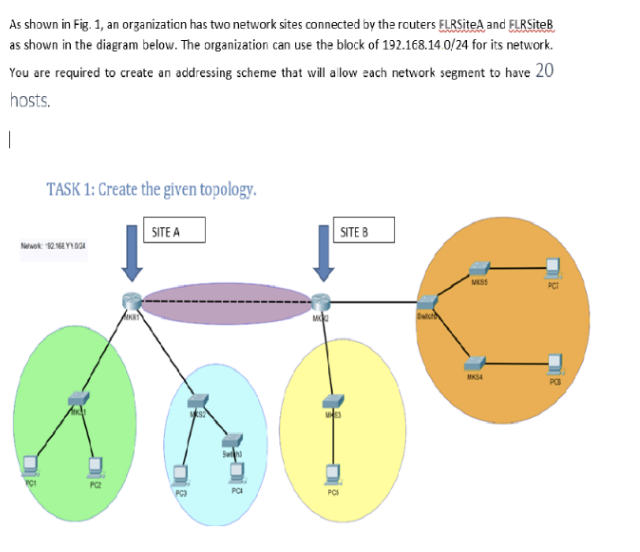
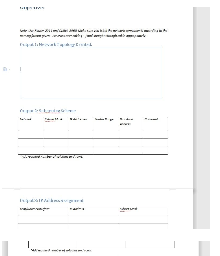
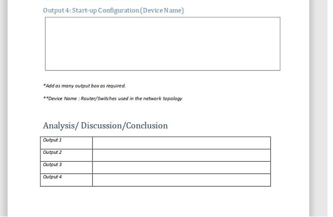
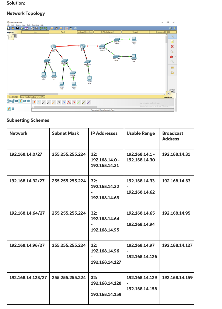
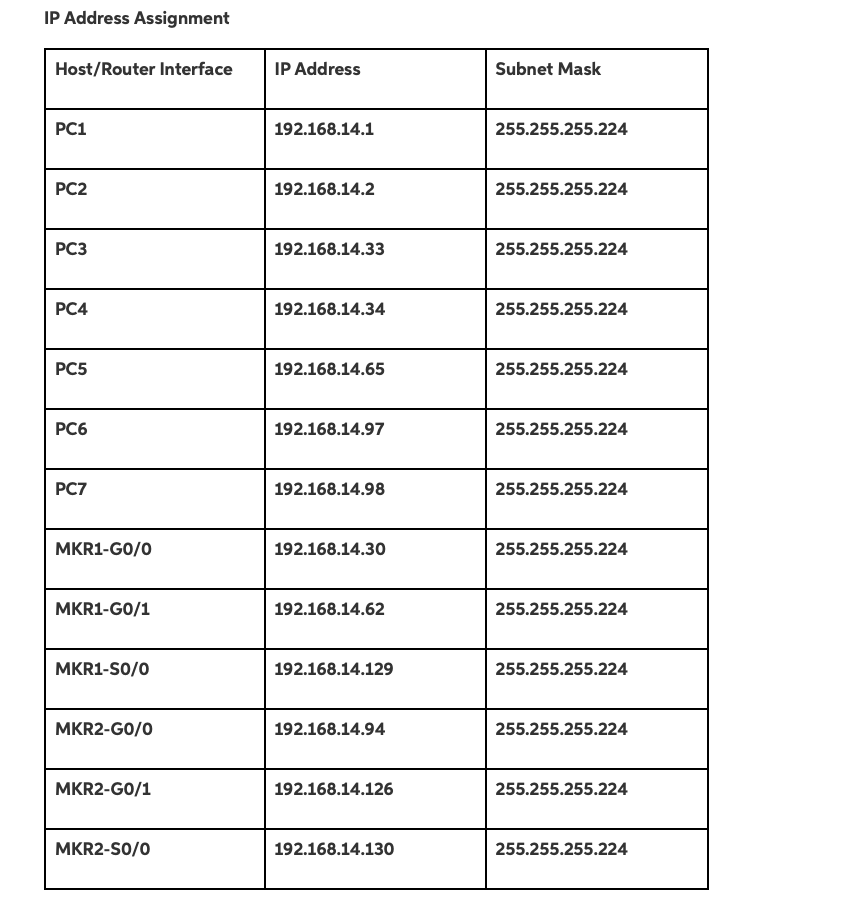
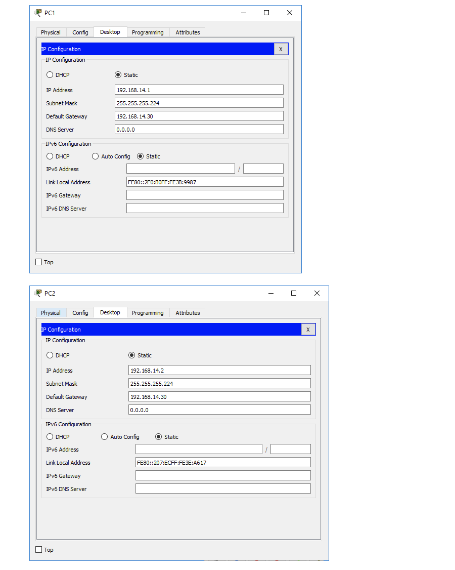
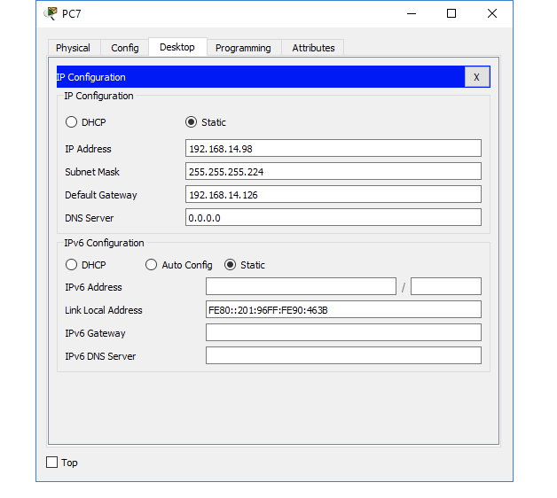
As shown in Fig. 1, an organization has two network sites connected by the routers FLRSiteA and FL SiteB as shown in the diagram below. The organization can use the block of 192.168.14.0/24 for its network You are required to create an addressing scheme that will allow each network segment to have 20 hosts. TASK 1: Create the given topology. SITE A SITE B 12.02 SS MX4 PG PCI vdjecuve: Note: Use Router 2911 and switch 2960. Make sure you label the network components according to the naming format given. Use cross over cable (---) and straight through cable appropriately. Output 1: Network Topology Created. Output 2: Subnetting Scheme Network Subnet Mask IP Addresses Usable Range Comment Broadcast Address *Add required number of columns and rows. Output 3: IP Address Assignment Host/Router Interface IP Address Subnet Mask *Add required number of columns and rows. Output 4: Start-up Configuration (Device Name) *Add as many output box as required. **Device Name : Router/Switches used in the network topology Analysis/ Discussion/Conclusion Output 1 Output 2 Output 3 Output 4 Solution: Network Topology DAG 0 Logical Root Heute Set Tied Badground B420 ni DI The 1320 12 77 Activate Windows Go to Settorit Windows Automatically Choo Carnection Type Subnetting Schemes Network Subnet Mask IP Addresses Usable Range Broadcast Address 192.168.14.0/27 255.255.255.224 192.168.14.31 32: 192.168.14.0 - 192.168.14.31 192.168.14.1 - 192.168.14.30 192.168.14.32/27 255.255.255.224 192.168.14.33 192.168.14.63 32: 192.168.14.32 192.168.14.62 192.168.14.63 192.168.14.64/27 255.255.255.224 192.168.14.65 192.168.14.95 32: 192.168.14.64 192.168.14.94 192.168.14.95 192.168.14.96/27 255.255.255.224 192.168.14.97 192.168.14.127 32: 192.168.14.96 192.168.14.126 192.168.14.127 192.168.14.128/27255.255.255.224 192.168.14.129 192.168.14.159 32: 192.168.14.128 192.168.14.158 192.168.14.159 IP Address Assignment Host/Router Interface IP Address Subnet Mask PC1 192.168.14.1 255.255.255.224 PC2 192.168.14.2 255.255.255.224 PC3 192.168.14.33 255.255.255.224 PC4 192.168.14.34 255.255.255.224 PC5 192.168.14.65 255.255.255.224 PC6 192.168.14.97 255.255.255.224 PC7 192.168.14.98 255.255.255.224 MKR1-G0/0 192.168.14.30 255.255.255.224 MKR1-G0/1 192.168.14.62 255.255.255.224 MKR1-S0/0 192.168.14.129 255.255.255.224 MKR2-G0/0 192.168.14.94 255.255.255.224 MKR2-G0/1 192.168.14.126 255.255.255.224 MKR2-S0/0 192.168.14.130 255.255.255.224 PC1 Physical Config Desktop Programming Attributes IP Configuration IP Configuration O DHCP O Static IP Address 192.168.14.1 Subnet Mask 255.255.255.224 Default Gateway 192.168.14.30 DNS Server 0.0.0.0 IPv6 Configuration O DHCP O Auto Config O Static IPv6 Address Link Local Address FE80::2E0:BOFF:FE3B:9987 IPv6 Gateway IPV6 DNS Server LTop PC2 X Physical Config Desktop Programming Attributes X IP Configuration IP Configuration O DHCP O Static IP Address 192.168.14.2 Subnet Mask 255.255.255.224 Default Gateway 192.168.14.30 DNS Server 0.0.0.0 IPv6 Configuration O DHCP Auto Config O Static IPv6 Address Link Local Address FE80::207:ECFF:FE3E:A617 IPV6 Gateway IPV6 DNS Server Top PC7 - Physical Config Desktop Programming Attributes IP Configuration IP Configuration DHCP Static IP Address 192.168.14.98 255.255.255.224 Subnet Mask 192.168.14. 126 Default Gateway DNS Server 0.0.0.0 IPv6 Configuration DHCP Auto Config Static IPv6 Address Link Local Address FE80::201:96FF:FE90:463B IPv6 Gateway IPv6 DNS Server Top As shown in Fig. 1, an organization has two network sites connected by the routers FLRSiteA and FL SiteB as shown in the diagram below. The organization can use the block of 192.168.14.0/24 for its network You are required to create an addressing scheme that will allow each network segment to have 20 hosts. TASK 1: Create the given topology. SITE A SITE B 12.02 SS MX4 PG PCI vdjecuve: Note: Use Router 2911 and switch 2960. Make sure you label the network components according to the naming format given. Use cross over cable (---) and straight through cable appropriately. Output 1: Network Topology Created. Output 2: Subnetting Scheme Network Subnet Mask IP Addresses Usable Range Comment Broadcast Address *Add required number of columns and rows. Output 3: IP Address Assignment Host/Router Interface IP Address Subnet Mask *Add required number of columns and rows. Output 4: Start-up Configuration (Device Name) *Add as many output box as required. **Device Name : Router/Switches used in the network topology Analysis/ Discussion/Conclusion Output 1 Output 2 Output 3 Output 4 Solution: Network Topology DAG 0 Logical Root Heute Set Tied Badground B420 ni DI The 1320 12 77 Activate Windows Go to Settorit Windows Automatically Choo Carnection Type Subnetting Schemes Network Subnet Mask IP Addresses Usable Range Broadcast Address 192.168.14.0/27 255.255.255.224 192.168.14.31 32: 192.168.14.0 - 192.168.14.31 192.168.14.1 - 192.168.14.30 192.168.14.32/27 255.255.255.224 192.168.14.33 192.168.14.63 32: 192.168.14.32 192.168.14.62 192.168.14.63 192.168.14.64/27 255.255.255.224 192.168.14.65 192.168.14.95 32: 192.168.14.64 192.168.14.94 192.168.14.95 192.168.14.96/27 255.255.255.224 192.168.14.97 192.168.14.127 32: 192.168.14.96 192.168.14.126 192.168.14.127 192.168.14.128/27255.255.255.224 192.168.14.129 192.168.14.159 32: 192.168.14.128 192.168.14.158 192.168.14.159 IP Address Assignment Host/Router Interface IP Address Subnet Mask PC1 192.168.14.1 255.255.255.224 PC2 192.168.14.2 255.255.255.224 PC3 192.168.14.33 255.255.255.224 PC4 192.168.14.34 255.255.255.224 PC5 192.168.14.65 255.255.255.224 PC6 192.168.14.97 255.255.255.224 PC7 192.168.14.98 255.255.255.224 MKR1-G0/0 192.168.14.30 255.255.255.224 MKR1-G0/1 192.168.14.62 255.255.255.224 MKR1-S0/0 192.168.14.129 255.255.255.224 MKR2-G0/0 192.168.14.94 255.255.255.224 MKR2-G0/1 192.168.14.126 255.255.255.224 MKR2-S0/0 192.168.14.130 255.255.255.224 PC1 Physical Config Desktop Programming Attributes IP Configuration IP Configuration O DHCP O Static IP Address 192.168.14.1 Subnet Mask 255.255.255.224 Default Gateway 192.168.14.30 DNS Server 0.0.0.0 IPv6 Configuration O DHCP O Auto Config O Static IPv6 Address Link Local Address FE80::2E0:BOFF:FE3B:9987 IPv6 Gateway IPV6 DNS Server LTop PC2 X Physical Config Desktop Programming Attributes X IP Configuration IP Configuration O DHCP O Static IP Address 192.168.14.2 Subnet Mask 255.255.255.224 Default Gateway 192.168.14.30 DNS Server 0.0.0.0 IPv6 Configuration O DHCP Auto Config O Static IPv6 Address Link Local Address FE80::207:ECFF:FE3E:A617 IPV6 Gateway IPV6 DNS Server Top PC7 - Physical Config Desktop Programming Attributes IP Configuration IP Configuration DHCP Static IP Address 192.168.14.98 255.255.255.224 Subnet Mask 192.168.14. 126 Default Gateway DNS Server 0.0.0.0 IPv6 Configuration DHCP Auto Config Static IPv6 Address Link Local Address FE80::201:96FF:FE90:463B IPv6 Gateway IPv6 DNS Server TopStep by Step Solution
There are 3 Steps involved in it
Step: 1

Get Instant Access to Expert-Tailored Solutions
See step-by-step solutions with expert insights and AI powered tools for academic success
Step: 2

Step: 3
Ace Your Homework with AI
Get the answers you need in no time with our AI-driven, step-by-step assistance
Get Started