Answered step by step
Verified Expert Solution
Question
1 Approved Answer
Required Tasks To design the cruise control system by applying the unified process, the designer must have at his disposal an initial domain model


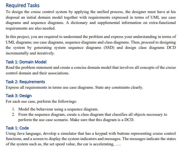
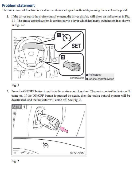
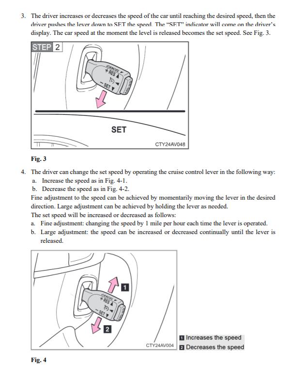
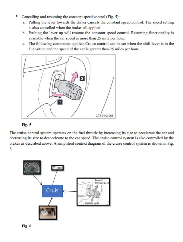
Required Tasks To design the cruise control system by applying the unified process, the designer must have at his disposal an initial domain model together with requirements expressed in terms of UML use case diagrams and scquence diagrams. A dictionary and supplemental information on extra-functional requirements are also needed. In this project, you are required to understand the problem and express your understanding in terms of UML diagrams; use case diagrams, sequence diagrams and class diagrams. Then, proceed to designing the system by generating system sequence diagrams (SSD) and design class diagrams DCD incrementally and iteratively. Task 1: Domain Model Read the problem statement and create a concise domain model that involves all concepts of the cruise control domain and their associations. Task 2: Requirements Express all requirements in terms use case diagrams. State any constraints clearly. Task 3: Design For each use case, perform the followings: 1. Model the behaviour using a sequence diagram. 2. From the sequence diagram, create a class diagram that classifies all objects necessary to perform the use case scenario. Make sure that this diagram is a DCD. Task 1: Code Using Java language, develop a simulator that has a keypad with buttons representing cruise control functions, and a screen to display the system indicators and messages. The messages indicate the states of the system such as, the set speed value, the car is accelerating. . Problem statement The cruise control function is used to maintain a set speed without depressing the accelerator pedal. 1. Ifthe driver starts the cruise control system, the driver display will show an indicator as in Fig. 1-1. The cruise control system is controlled via a lever which has many switches on it as shown in Fig. 1-2. SET 2 Indicators CTY24AVO01 a Cruise control switch Fig. 1 2. Press the ON/OFF button to activate the cruise control system. The cruise control indicator will come on. If the ON/OFF button is pressed on again, then the cruise control system will be deactivated, and the indicator will come off. See Fig. 2. STEP 1 + RES -SET V CTY24AVO47 Fig. 2 3. The driver increases or decreases the speed of the car until reaching the desired speed, then the driver pushes the lever down to SET the speed The "SET" indicator will come on the driver's display. The car speed at the moment the level is released becomes the set speed. See Fig. 3. STEP 2 + RES - SET Y SET CTY24AV048 4. The driver can change the set speed by operating the cruise control lever in the following way: a. Increase the speed as in Fig. 4-1. b. Decrease the speed as in Fig. 4-2. Fine adjustment to the speed can be achieved by momentarily moving the lever in the desired direction. Large adjustment can be achieved by holding the lever as needed. The set speed will be increased or decreased as follows: a. Fine adjustment: changing the speed by 1 mile per hour each time the lever is operated. Fig. 3 b. Large adjustment: the speed can be increased or decreased continually until the lever is released. CANCEL + RES -SET IIncreases the speed CTY24AV004 2 Decreases the speed Fig. 4 5. Cancelling and resuming the constant speed control (Fig. 5): a. Pulling the lever towards the driver cancels the constant speed control. The speed setting is also cancelled when the brakes all applied. b. Pushing the lever up will resume the constant speed control. Resuming functionality is available when the car speed is more than 25 mile per hour. c. The following constraints applies: Cruise control can be set when the shift lever is in the D position and the speed of the car is greater than 25 miles per hour. 2 CANCTL +RES SET CT24AVO05 The cruise control system operates on the fuel throttle by increasing its size to accelerate the car and decreasing its size to deaccelerate to the car speed. The cruise control system is also controlled by the Fig. 5 brakes as described above. A simplified context diagram of the cruise control system is shown in Fig. 6. NISET Resume Increase speed Cruis Cance Decrease speed Fig. 6
Step by Step Solution
★★★★★
3.43 Rating (153 Votes )
There are 3 Steps involved in it
Step: 1
Based on the problem statement we can start by understanding the concepts and interactions in the cruise control domain to create the domain model Task 1 Task 1 Domain Model The domain model involves ...
Get Instant Access to Expert-Tailored Solutions
See step-by-step solutions with expert insights and AI powered tools for academic success
Step: 2

Step: 3

Ace Your Homework with AI
Get the answers you need in no time with our AI-driven, step-by-step assistance
Get Started


