How do i include the segdisplay and write the behavioral code together in desgin source of verligo.

The segdisplay is given below
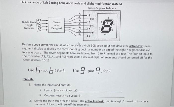
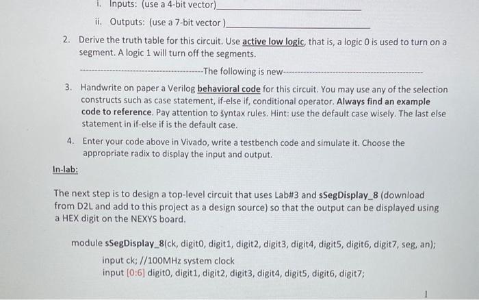
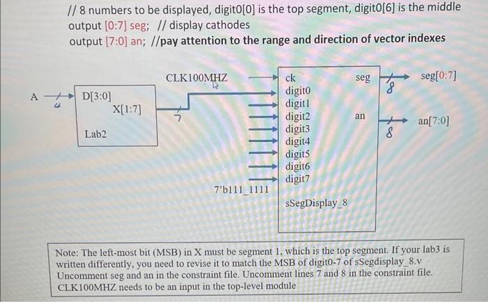
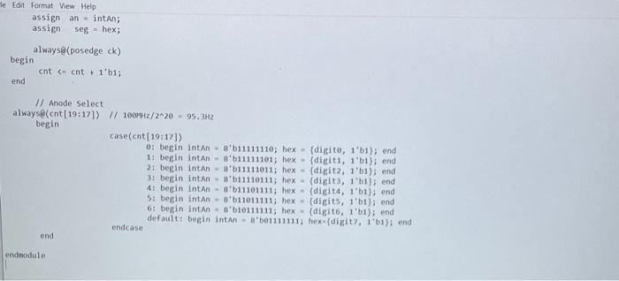
This is a re-do of Lab 2 using behavioral code and slight modification instead. Seven-Seement Indieafor Design a code converter circuit which receivs a 4-bit BCD code input and drives the active-low sevensegment display to display the corresponding decimal number on one of the eight 7 -segment displays in Nexys board. The seven segments here are labeled from 1 to 7 instead of a to g. The four-bit input to the converter (A3,A2,A1, and AO) represents a decimal digit. All segments should be turned off for the decimal values 10-15. Use ( not ) for 6 . Use (not ) for 9 . Pre-lab: 1. Name the inputs and outputs. i. Inputs: (use a 4-bit vector). ii. Outputs: (use a 7-bit vector). 2. Derive the truth table for this circuit. Use active low logic, that is, a logic 0 is used to turn on a seement. A loeic 1 will turn off the seements. i. Inputs: (use a 4-bit vector) ii. Outputs: (use a 7-bit vector) 2. Derive the truth table for this circuit. Use active low logic, that is, a logic 0 is used to turn on a segment. A logic 1 will turn off the segments. The following is new 3. Handwrite on paper a Verilog behavioral code for this circuit. You may use any of the selection constructs such as case statement, if-else if, conditional operator. Always find an example code to reference. Pay attention to yntax rules. Hint: use the default case wisely. The last else statement in if-else if is the default case. 4. Enter your code above in Vivado, write a testbench code and simulate it. Choose the appropriate radix to display the input and output. In-lab: The next step is to design a top-level circuit that uses Lab\#3 and sSegDisplay_ 8 (download from D2L and add to this project as a design source) so that the output can be displayed using a HEX digit on the NEXYS board. module sSegDisplay_8(ck, digit0, digit1, digit2, digit3, digit4, digit5, digit6, digit7, seg, an); input ck; //100MHz system clock input [0:6] digit0, digit1, digit2, digit3, digit4, digit5, digit6, digit7; // 8 numbers to be displayed, digit0[0] is the top segment, digit0 [6] is the middle output [0:7] seg; // display cathodes output [7:0] an; //pay attention to the range and direction of vector indexes Note: The left-most bit (MSB) in X must be segment 1 , which is the top segment. If your lab3 is written differently, you need to revise it to match the MSB of digit0-7 of sSegdisplay 8.v Uncomment seg and an in the constraint file. Uncomment lines 7 and 8 in the constraint file. CLK100MHZ needs to be an input in the top-level module Edit format View Help assign an = intAn; assign seg = hex; alwaysg (posedge ck ) begin end cnt=cnt+1b1; 11 Anode select alwayse(cnt [19:17])//160HHz/220=95.3Hz beein case(cot[19:17]) 0: begin intan = 8b11111119; hex ={digit,1+b1}; and 1: begin intan =8b11111101; hex ={digit1,1b1}; end 2: begin intan = 8b11111011; hex =(digit2,1b1); end 3: begin intan =8b11110111; hex =(digit3,1b1); end 4: begin intan = 8'b111e1111; hex = (digitd, 1+b1 ) end 5: begin intan - 8'b11e11111; hex = (digits, 1'b1); end 6: beggin intan =0b10111111; hex ={digit6,1b1}; end default: begdn intAn =8b01111111; hexn (digit7,1 bs ) i end end endcase endmodule


