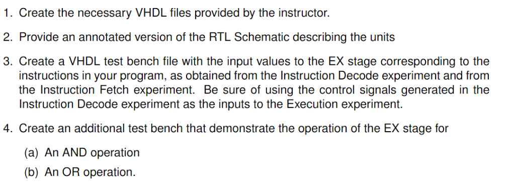
I created a testbench, but it is incomplete. Below is the code that was provided and the testbench.
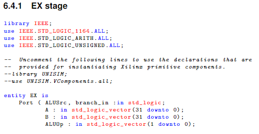
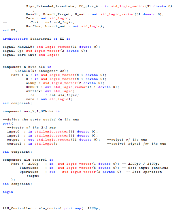
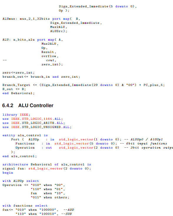
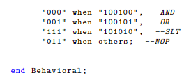
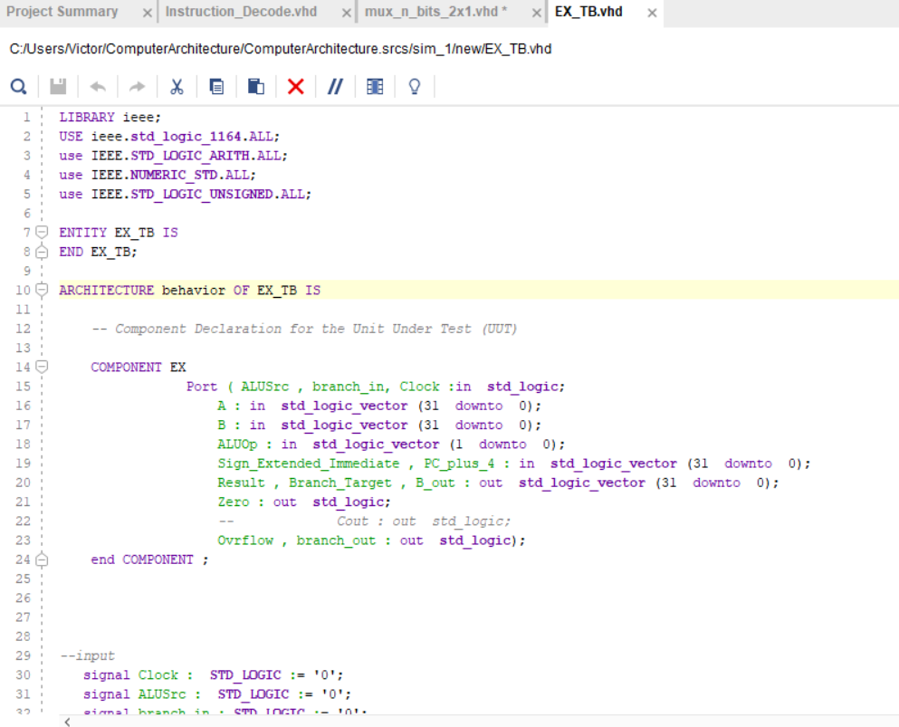
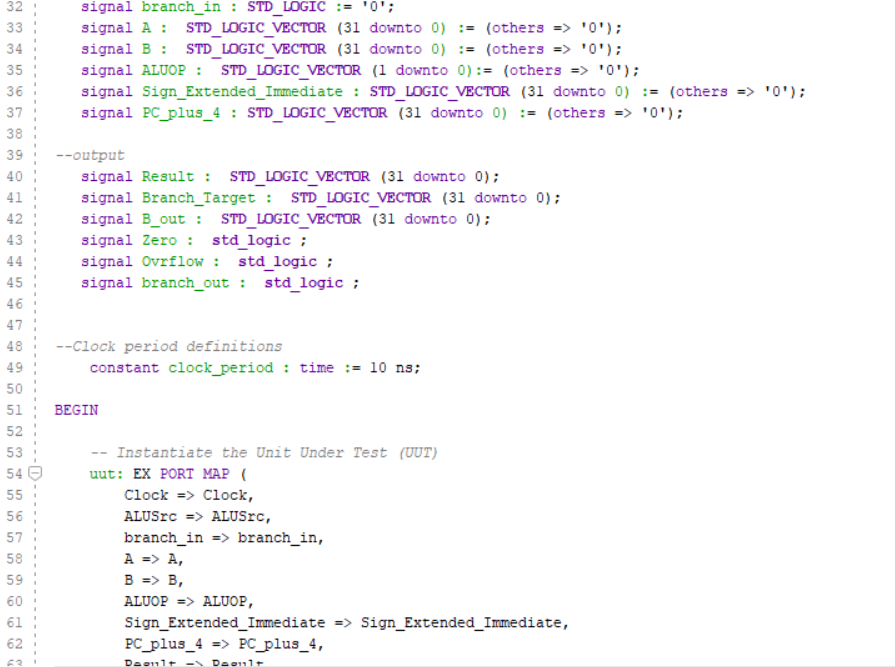
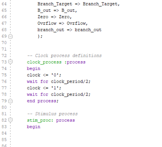
1. Create the necessary VHDL files provided by the instructor. 2. Provide an annotated version of the RTL Schematic describing the units 3. Create a VHDL test bench file with the input values to the EX stage corresponding to the instructions in your program, as obtained from the Instruction Decode experiment and from the Instruction Fetch experiment. Be sure of using the control signals generated in the Instruction Decode experiment as the inputs to the Execution experiment. 4. Create an additional test bench that demonstrate the operation of the EX stage for (a) An AND operation (b) An OR operation. 6.4.1 EX stage library IEEE; use IEEE. STD LOGIC_1164. ALL; use IEEE.STD use IEEE. STD_LOGIC_UNSIGNED.ALL; LOGIC_ARITH. ALL; Uncomment the following lines to use the declarations that are pTovided for instantiating Xilinz primitive components --library UNISIM; use UNISIM.VComponents.all entity EX is Port ALUSrc, branch_in :in atd logic A in std_logic vector (31 downto 0); B in atd_logic vector (31 downto 0) ALUOp in atd_logic_vector ( downto 0) Sign_Extended_Immediate, PC-plus-4: in atd_logic vector (31 dovnto 0) Result, Branch_Target, B.out : out atd_logic vector (31 downto 0) Zero: out std_logic; Cout out std.logic Ovrflow, branch out out std_logic) end EX; architecture Behavioral of EX is signal Mux2ALU: std_logic vector (31 downto 0) signal Op:atd_logic_vector (2 downto o) signal zero_int: std.logic component n_bits alu is GENERIC (N: integer:= 32); Port A : in std_logic vector(N-1 dovnto 0) B in std_logic vector(N-1 downto 0) ALUOp std_logic vector (2 downto 0) RESULT :out std_logic.vector (N-1 downto 0) ovrflow: out std.logic; Co : out stdlogic; zero out std_logic) end component; component mux 2_1_32bits is --define the ports needed in the muc port -inputs of the 2:1 muz inputo : in std_logic vector (31 downto 0) input : in std_logic vector (31 downto 0) utput : out std_logic vector (31 donto 0)-output of the muz control : in std_logic); -control signal for the muz end component; component alu control is Port ALUOp: in std_logic_vector (1 downto 0) -ALUUpOALUUp1 Functions : in std-logic-vector (5 downto 0); -- 6bit input funtions Operationout astd_logic vector (2 downto 0)3bit operation output end component; begin ALU Controller alu control port map ALUOp, 000"when 100100", --AND 001 when "100101", --OR "111" when "101010", -SLT 011 when others; NOP end Behavioral; Project Summary x! Instruction-Decode.vhd xlmux-n-bits-2x1.vhd. 1 EXTB.vhd - C:/UsersVictor/ComputerArchitecture/ComputerArchitecture.srcs/sim_1ewIEX_TB.vhd 1LIBRARY ieee; 2 USE ieee.std logic 1164.ALL; 3use IEEE. STD LOGIC ARITH.ALL 4use IEEE. NUMERIC STD.ALL; 5use IEEE. STD LOGIC_UNSIGNED.ALL; 7 ENTITY EX_TB IS 8END EX TB: 10ARCHITECTURE behavior OF EX TB IS Component Declaration for the Unit Under Test (UUT) 13 14COMPONENT EX 15 16 Port ( ALUSrc , branch_in, Clock :in std logic; 18 19 20 21 A : in std logic vector (31 downto 0) B: in std logic vector (3l downto 0); ALUOp in std logic_vector (1 downto 0) Sign_Extended_Iamediate PC plus_4: in std logic vector (31 downto 0) Result Branch Target B out: out std logic vector (31 downto 0) Zero:out std logic; Cout: out std logic 23 24 25 26 27 28 29 30 31 Ovrflowbranch out:out std logic) end COMPONENT iput signal Clock STD LOGIC'0 signal ALUSrcSTD LOGIC-'0 32 signal branch_in STD LOGIC '0'; signal A STD LOGIC VECTOR (31 downto 0(others '0 signal B : STD LOGIC VECTOR (31 downto 0) := (others '0'); signal ALUOP : STD LOGIC VECTOR (1 downto 0) := (others => '0' ); signal Sign_Extended_Immediate: STD LOGIC VECTOR (31 downto 0)(others -'0'); signal PC plus_4 : STD LOGIC VECTOR (31 downto 0)-(others-'0') 34 . 35 36 37 38 39 40 41 42 43 output Signal Result STD LOGIC VECTOR (31 downto 0 signal Branch_Target STD_LOGIC VECTOR (31 downto 0) signal B_out: STD LOGIC VECTOR (31 downto 0) signal Zerostd logic signal Ovrflow: std_logic: signal branch_out: std logic: 45 471 Clock period definitions 49 50 51 BEGIN 52 53 546 uut : EXPORT MAP ( constant clock_period:time 10 ns; Instantiate the Unit Under Test (UUT) Clock => Clock, 56 57 58 59 60 61 62 branch in -> branch in A -> A, Sign Extended immediate => Sign Extended Immediate, PC plus_4 -> PCplus_4, 64 65 Branch_Target Branch_Target, B_out -> B out, 67 68 69 70 71 72 73 74 75 76 branch outbranch out Clock process definitions clock _process process begin clock '0' ); signal Sign_Extended_Immediate: STD LOGIC VECTOR (31 downto 0)(others -'0'); signal PC plus_4 : STD LOGIC VECTOR (31 downto 0)-(others-'0') 34 . 35 36 37 38 39 40 41 42 43 output Signal Result STD LOGIC VECTOR (31 downto 0 signal Branch_Target STD_LOGIC VECTOR (31 downto 0) signal B_out: STD LOGIC VECTOR (31 downto 0) signal Zerostd logic signal Ovrflow: std_logic: signal branch_out: std logic: 45 471 Clock period definitions 49 50 51 BEGIN 52 53 546 uut : EXPORT MAP ( constant clock_period:time 10 ns; Instantiate the Unit Under Test (UUT) Clock => Clock, 56 57 58 59 60 61 62 branch in -> branch in A -> A, Sign Extended immediate => Sign Extended Immediate, PC plus_4 -> PCplus_4, 64 65 Branch_Target Branch_Target, B_out -> B out, 67 68 69 70 71 72 73 74 75 76 branch outbranch out Clock process definitions clock _process process begin clock


