

Question: I have the solution, but can anyone explain to me how to reach the final output? A diagram would be nice. Given the following implementation
I have the solution, but can anyone explain to me how to reach the final output? A diagram would be nice.
Given the following implementation of a gated(clocked) S-R latch
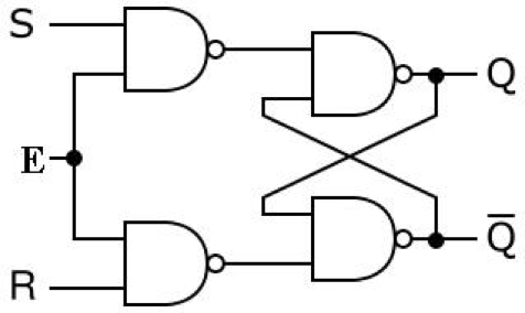
fill in its truth table:
| E | Q(t) | S(t) | R(t) | Q(t+1) |
| 0 | 0 | 0 | 0 | 0 |
| 0 | 0 | 0 | 1 | 0 |
| 0 | 0 | 1 | 0 | 0 |
| 0 | 0 | 1 | 1 | 0 |
| 0 | 1 | 0 | 0 | 1 |
| 0 | 1 | 0 | 1 | 1 |
| 0 | 1 | 1 | 0 | 1 |
| 0 | 1 | 1 | 1 | 1 |
| 1 | 0 | 0 | 0 | 0 |
| 1 | 0 | 0 | 1 | 0 |
| 1 | 0 | 1 | 0 | 1 |
| 1 | 0 | 1 | 1 | ? |
| 1 | 1 | 0 | 0 | 1 |
| 1 | 1 | 0 | 1 | 0 |
| 1 | 1 | 1 | 0 | 1 |
| 1 | 1 | 1 | 1 | ? |
use ? for undefined states (i.e., when ).
Q(t), S(t), R(t) are the values of Q, S and R at time t, while Q(t+1) is the value of Q at time t+1 (after applying new inputs).
[O S
Step by Step Solution
There are 3 Steps involved in it
1 Expert Approved Answer
Step: 1 Unlock

Question Has Been Solved by an Expert!
Get step-by-step solutions from verified subject matter experts
Step: 2 Unlock
Step: 3 Unlock