Answered step by step
Verified Expert Solution
Question
1 Approved Answer
I just need Part 4 needed, however part 3 is necessary to complete part 4. Thanks for the Help! Part III - VHDL: One-bit Full


I just need Part 4 needed, however part 3 is necessary to complete part 4. Thanks for the Help!
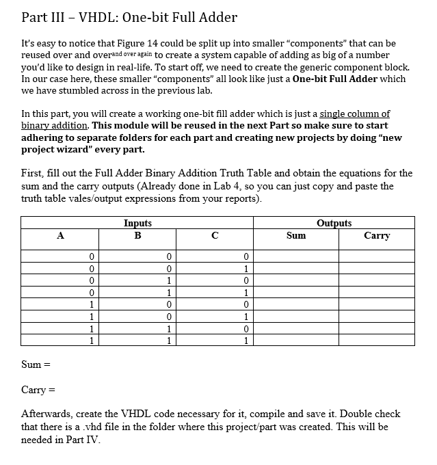
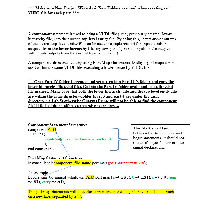
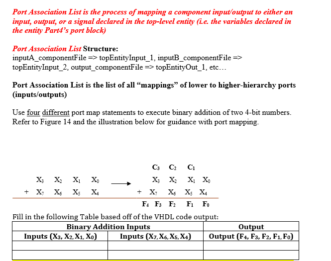
Part III - VHDL: One-bit Full Adder It's easy to notice that Figure 14 could be split up into smaller "components that can be reused over and overand over again to create a system capable of adding as big of a number you'd like to design in real-life. To start off, we need to create the generic component block. In our case here, these smaller "components" all look like just a One-bit Full Adder which we have stumbled across in the previous lab. In this part, you will create a working one-bit fill adder which is just a single column of binary addition. This module will be reused in the next Part so make sure to start adhering to separate folders for each part and creating new projects by doing new project wizard" every part. First, fill out the Full Adder Binary Addition Truth Table and obtain the equations for the sum and the carry outputs (Already done in Lab 4, so you can just copy and paste the truth table vales/output expressions from your reports). Inputs B Outputs Sum A Carry 0 0 0 0 1 0 1 0 0 0 1 0 1 1 1 1 1 0 0 1 1 1 0 1 Sum= Carry = Afterwards, create the VHDL code necessary for it, compile and save it. Double check that there is a vhd file in the folder where this project/part was created. This will be needed in Part IV. *** Make sure New Project Wizards & New Folders are used when creating each VHDL file for each part. *** A component statement is used to bring a VHDL file (.vhd) previously created (lower hierarchy file) into the current, top-level entity file. By doing this, inputs and/or outputs of the current top-level entity file can be used as a replacement for inputs and/or outputs from the lower hierarchy file (replacing the generic inputs and/or outputs with inputs/outputs from the current top-level created). A component file is executed by using Port Map statements. Multiple port maps can be|| used within the same VHDL file, executing a lower hierarchy VHDL file. ***Once Part IV folder is created and set up, go into Part III's folder and copy the lower hierarchy file (.vhd file). Go into the Part IV folder again and paste the.yhd file in there. Make sure that both the lower hierarchy file and the top level entity file are within the same directory/folder (part 3 and part 4 are under the same directory, i.e Lab 5) otherwise Quartus Prime will not be able to find the component file! It fails at doing effective recursive searching.... Component Statement Structure: component Part3 PORT inputs/outputs of the lower-hierarchy file ); end component; . } This block should go in between the Architecture and begin statements. It should not matter if it goes before or after signal declarations. Port Map Statement Structure: instance_label: component_file_name port map (port_association_list); for example: Labels_can_be_named_whatever: Part3 port map (a=> x1(1), b => x2(1),c=> 0), sum -> f(1), carry => c(1)); The port map statements will be declared in between the "begin and end block. Each on a new line, separated by a ";'. Port Association List is the process of mapping a component input/output to either an input, output, or a signal declared in the top-level entity (i.e. the variables declared in the entity Part4's port block) Port Association List Structure: inputA_componentFile => topEntityInput_1, inputB_componentFile => topEntityInput_2, output_componentFile => topEntityOut_1, etc... Port Association List is the list of all mappings" of lower to higher-hierarchy ports (inputs/outputs) Use four different port map statements to execute binary addition of two 4-bit numbers. Refer to Figure 14 and the illustration below for guidance with port mapping. C3 C2 Ci Xo X; X2 X X3 X X X + X X X X + X X6 X5 X4 F4 F3 F2 F Fo Fill in the following Table based off of the VHDL code output: Binary Addition Inputs Output Inputs (X3, X2, X1, Xo) Inputs (X7, X6, Xs, X4) Output (F4, F3, F2, F1, F0)Step by Step Solution
There are 3 Steps involved in it
Step: 1

Get Instant Access to Expert-Tailored Solutions
See step-by-step solutions with expert insights and AI powered tools for academic success
Step: 2

Step: 3

Ace Your Homework with AI
Get the answers you need in no time with our AI-driven, step-by-step assistance
Get Started


