

Question: I need answers for this lab please. 6 suffixes PHY1007C E4a: Simple D.C. Circuits Introduction: An oft unexplored, but extremely important component of modern life
I need answers for this lab please. 6 suffixes PHY1007C
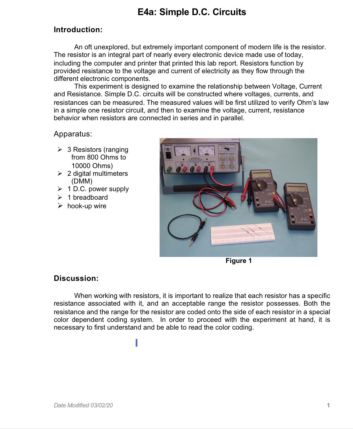
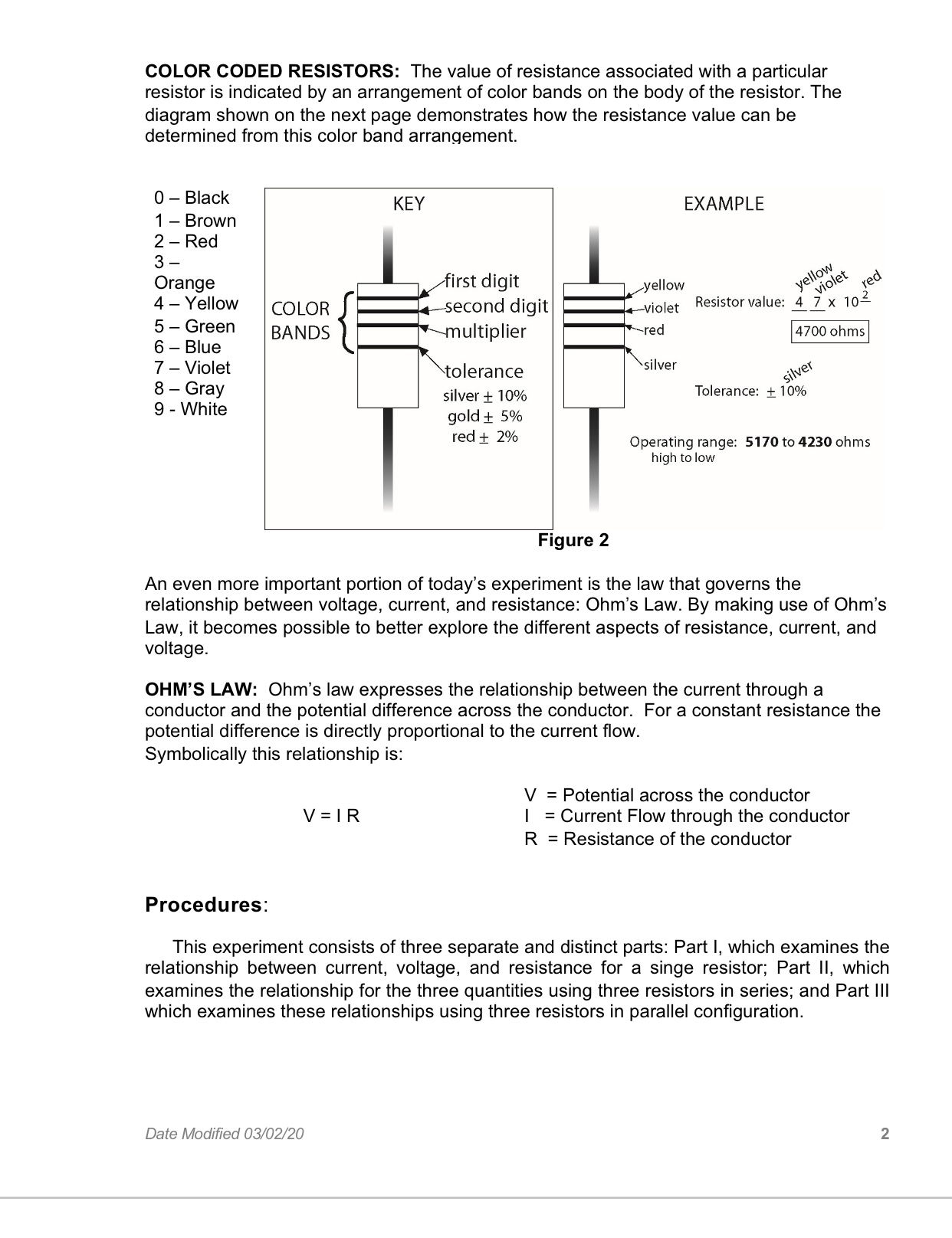
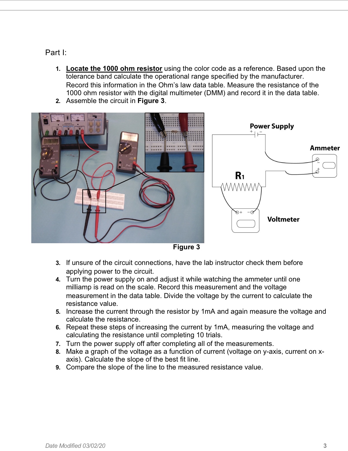
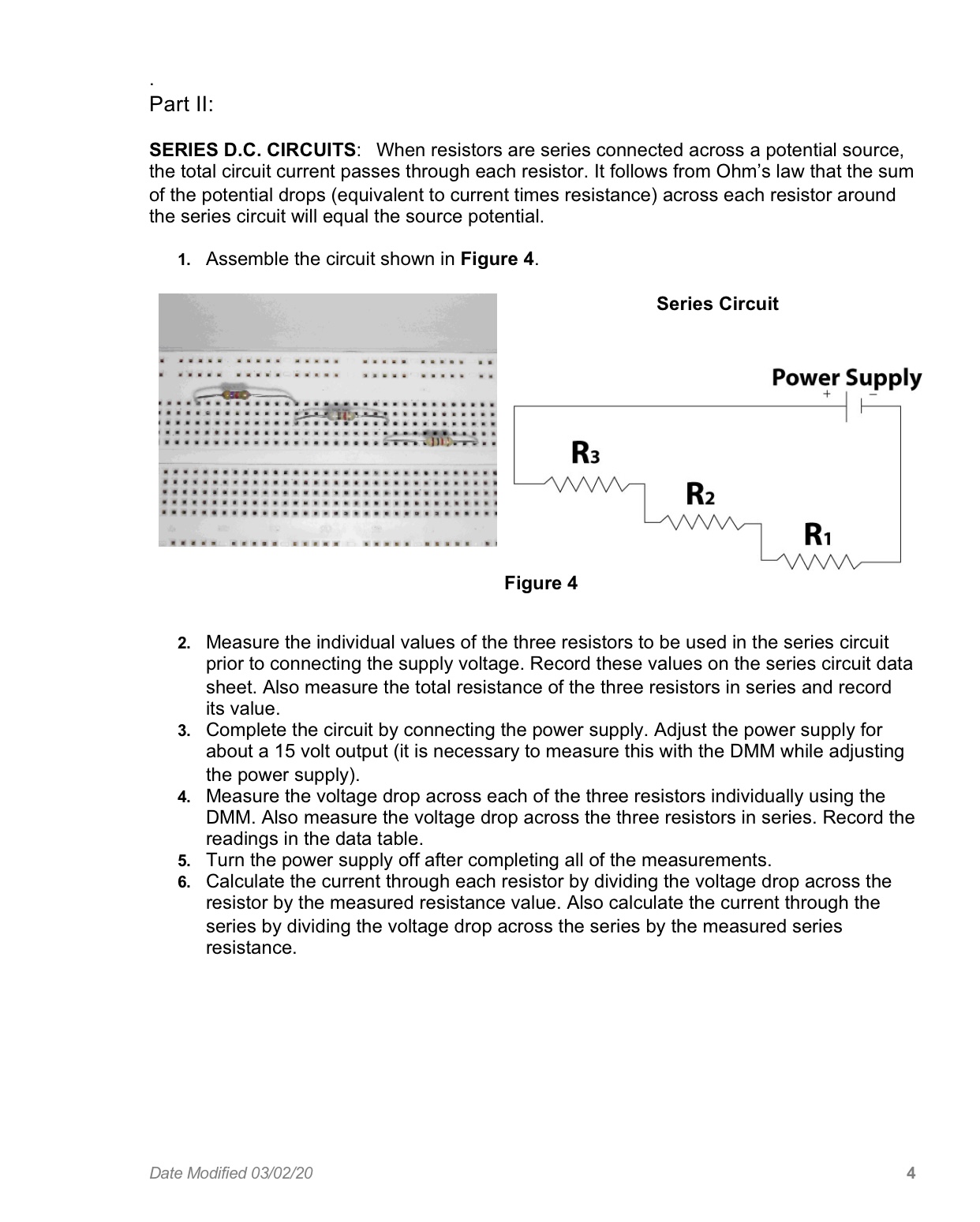
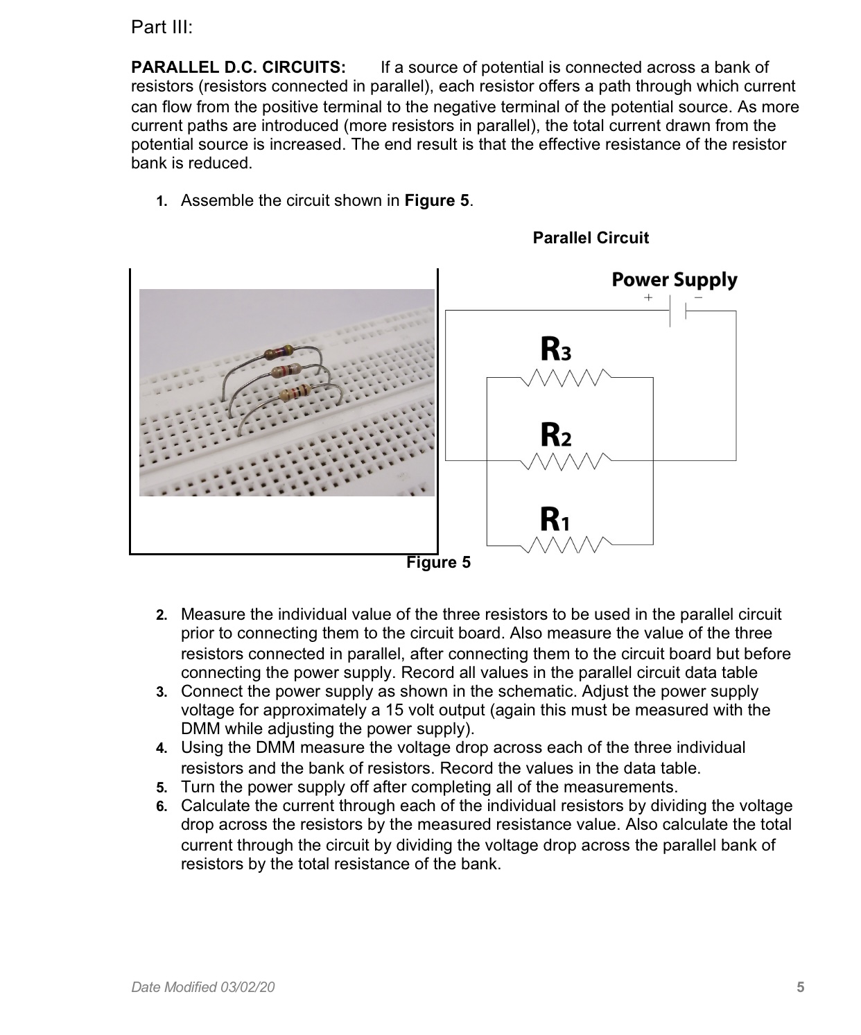
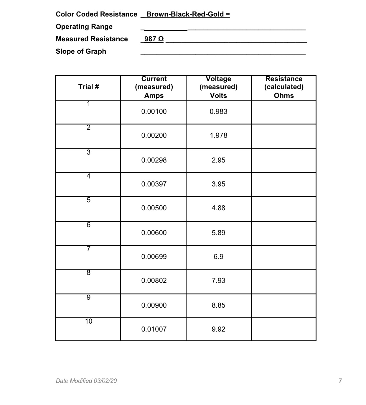
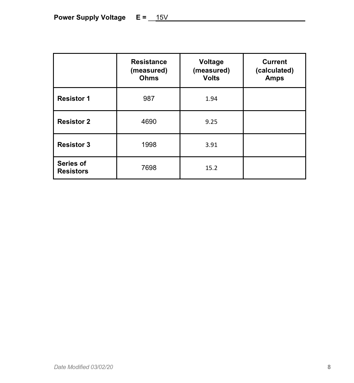
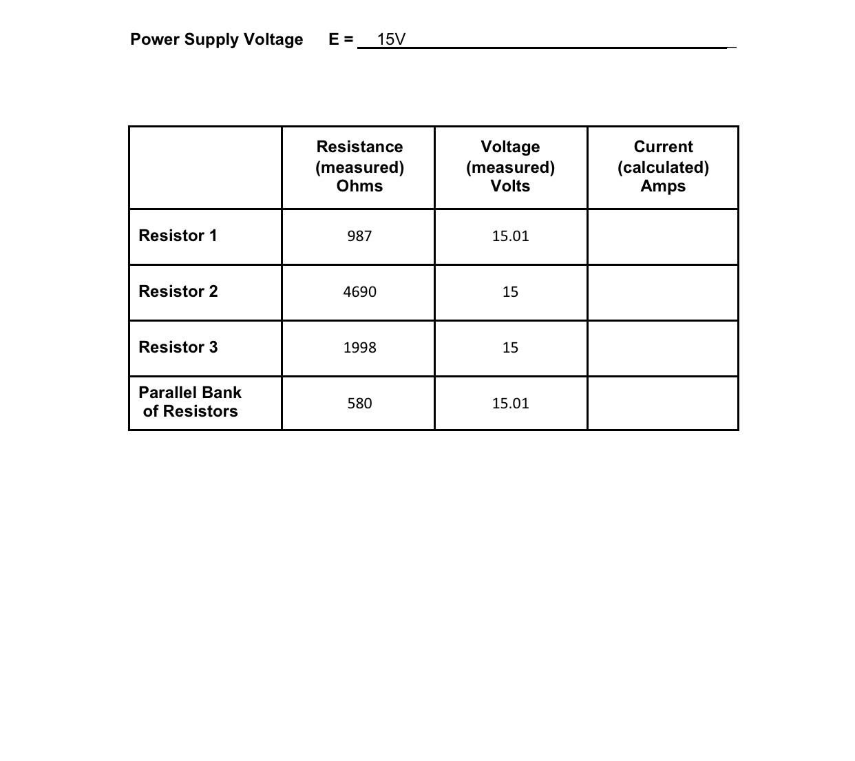
E4a: Simple D.C. Circuits Introduction: An oft unexplored, but extremely important component of modern life is the resistor. The resistor is an integral part of nearly every electronic device made use of today, including the computer and printer that printed this lab report. Resistors function by provided resistance to the voltage and current of electricity as they ow through the different electronic components. This experiment is designed to examine the relationship between Voltage, Current and Resistance. Simple D.C. circuits will be constructed where voltages. currents, and resistances can be measured. The measured values will be rst utilized to verify Ohm's law in a simple one resistor circuit, and then to examine the voltage, current, resistance behavior when resistors are connected in series and in parallel. Apparatus: > 3 Resistors (ranging from 800 Ohms to 10000 Ohms) E 2 digital multimeters (DMM) ;; 1 D.C. power supply 3 1 breadboard > hook-up wire Discussion: When working with resistors, it is important to realize that each resistor has a specic resistance associated with it, and an acceptable range the resistor possesses. Both the resistance and the range for the resistor are coded onto the side of each resistor in a special color dependent coding system. In order to proceed with the experiment at hand, it is necessary to rst understand and be able to read the color coding. Date Modied 03/02/20 1 COLOR CODED RESISTORS: The value of resistance associated with a particular resistor is indicated by an arrangement of color bands on the body of the resistor. The diagram shown on the next page demonstrates how the resistance value can be determined from this color band arrangement. o Black KEY EXAMPLE 1 Brown 2 Red 3 _ - ' ' \\0'\" x c Orange first digit yellow a'ixow 3e. 4 Yellow COLOR second digit violet Resistor value: ilx 10* 2- green BANDS ultiplier red [:4700 ohms U9 7 Violet tolerance Silver we" 8 _ Gray silver :I: 10% Tolerance: i 10% 9 ' Whlte gold i 5% red i 2% Operating range: 5170 to 4230 ohms high to low Figure 2 An even more important portion of today's experiment is the law that governs the relationship between voltage, current, and resistance: Ohm's Law. By making use of Ohm's Law, it becomes possible to better explore the different aspects of resistance, current, and voltage. OHM'S LAW: Ohm's law expresses the relationship between the current through a conductor and the potential difference across the conductor. For a constant resistance the potential difference is directly proportional to the current ow. Symbolically this relationship is: V = Potential across the conductor V = l R l = Current Flow through the conductor R = Resistance of the conductor Procedu res: This experiment consists of three separate and distinct parts: Part I, which examines the relationship between current, voltage, and resistance for a singe resistor; Part II, which examines the relationship for the three quantities using three resistors in series; and Part III which examines these relationships using three resistors in parallel conguration. Date Modied 03/02/20 2 Part I: 1. Locate the 1000 ohm resistor using the color code as a reference. Based upon the tolerance band calculate the operational range specied by the manufacturer. Record this information in the Ohm's law data table. Measure the resistance of the 1000 ohm resistor with the digital multimeter (DMM) and record it in the data table. 2. Assemble the circuit in Figure 3. rower Supply 7 Ammeter Voltmeter Figure 3 3. If unsure of the circuit connections, have the lab instructor check them before applying power to the circuit. 4. Turn the power supply on and adjust it while watching the ammeter until one milliamp is read on the scale. Record this measurement and the voltage measurement in the data table. Divide the voltage by the current to calculate the resistance value. 5. Increase the current through the resistor by 1mA and again measure the voltage and calculate the resistance. 6. Repeat these steps of increasing the current by 1mA, measuring the voltage and calculating the resistance until completing 10 trials. 7. Turn the power supply off after completing all of the measurements. 3. Make a graph of the voltage as a function of current (voltage on y-axis, current on x- axis). Calculate the slope of the best t line. 9. Compare the slope of the line to the measured resistance value. Date Modied 03/02/20 3 Part II: SERIES D.C. CIRCUITS: When resistors are series connected across a potential source, the total circuit current passes through each resistor. It follows from Ohm's law that the sum of the potential drops (equivalent to current times resistance) across each resistor around the series circuit will equal the source potential. 1. Assemble the circuit shown in Figure 4. Series Circuit Power Supply R3 R2 mm R1 Figure 4 2. Measure the individual values of the three resistors to be used in the series circuit prior to connecting the supply voltage. Record these values on the series circuit data sheet. Also measure the total resistance of the three resistors in series and record its value. 3. Complete the circuit by connecting the power supply. Adjust the power supply for about a 15 volt output (it is necessary to measure this with the DMM while adjusting the power supply). . Measure the voltage drop across each of the three resistors individually using the DMM. Also measure the voltage drop across the three resistors in series. Record the readings in the data table. . Turn the power supply off after completing all of the measurements. 6. Calculate the current through each resistor by dividing the voltage drop across the resistor by the measured resistance value. Also calculate the current through the series by dividing the voltage drop across the series by the measured series resistance. Date Modified 03/02/20Part III: PARALLEL D.C. CIRCUITS: If a source of potential is connected across a bank of resistors (resistors connected in parallel), each resistor offers a path through which current can flow from the positive terminal to the negative terminal of the potential source. As more current paths are introduced (more resistors in parallel), the total current drawn from the potential source is increased. The end result is that the effective resistance of the resistor bank is reduced. 1. Assemble the circuit shown in Figure 5. Parallel Circuit PowerSupply + l | | R3 Igure 5 2. Measure the individual value of the three resistors to be used in the parallel circuit prior to connecting them to the circuit board. Also measure the value of the three resistors connected in parallel. after connecting them to the circuit board but before connecting the power supply. Record all values in the parallel circuit data table 3. Connect the power supply as shown in the schematic. Adjust the power supply voltage for approximately a 15 volt output (again this must be measured with the DMM while adjusting the power supply). 4. Using the DMM measure the voltage drop across each of the three individual resistors and the bank of resistors. Record the values in the data table. Turn the power supply off after completing all of the measurements. Calculate the current through each of the individual resistors by dividing the voltage drop across the resistors by the measured resistance value. Also calculate the total current through the circuit by dividing the voltage drop across the parallel bank of resistors by the total resistance of the bank. 9'!\" Date Modied 03/02/20 5 Color Coded Resistance _Brown-Black-Red-Gold = Operating Range Measured Resistance 987 0 Slope of Graph Current Voltage Resistance Trial # (measured) (measured) (calculated) Amps Volts Ohms 0.00100 0.983 2 0.00200 1.978 3 0.00298 2.95 4 0.00397 3.95 5 0.00500 4.88 6 0.00600 5.89 0.00699 6.9 0.00802 7.93 9 0.00900 8.85 10 0.01007 9.92 Date Modified 03/02/20 7Power Supply Voltage E = 15V Resistance Voltage Current (measured) (measured) (calculated) Ohms Volts Amps Resistor 1 987 1.94 Resistor 2 4690 9.25 Resistor 3 1998 3.91 Series of 7698 Resistors 15.2 Date Modified 03/02/20 8Power Supply Voltage E = 15V Resistance Voltage Current (measured) (measured) (calculated) Ohms Volts Amps Parallel Bank of Resistors
Step by Step Solution
There are 3 Steps involved in it

Get step-by-step solutions from verified subject matter experts