I need help writing the code fore step 3. I am using MPLAB X IDE and PICSimLab.
Here is the code I have so far.
#include
#pragma config WDT = OFF
#define _XTAL_FREQ 16000000
#include "lcd.h"
int i;
void adc_init(void)
{ ADCON0 = 0b00000001;
ADCON1 = 0b00000000;
ADCON2 = 0b10001000;
TRISA = 0b00000001;
}
int adc_read(void) { ADCON0bits.GODONE = 1;
while(ADCON0bits.GODONE == 1);
i = ADRES;
return i; }
void main(void) {
TRISD = 0x00;
adc_init();
lcd_init();
lcd_str("Hello World");
while(1) {
i = adc_read();
LATD = i;
lcd_dat();
__delay_ms(100);
}
}
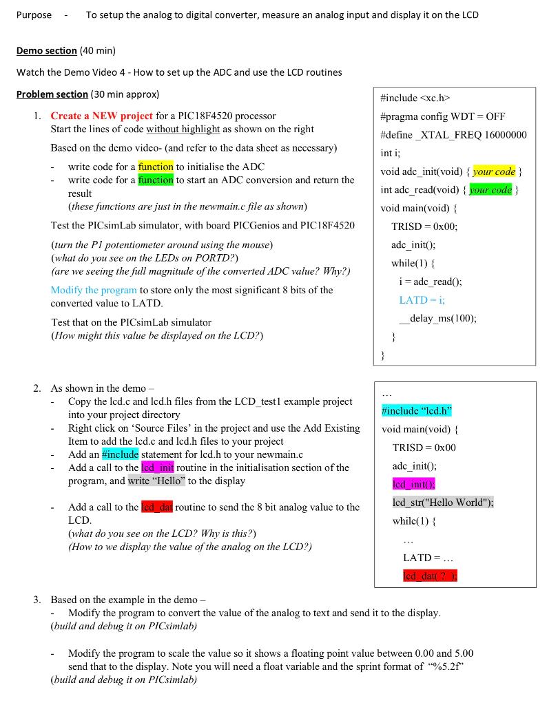
Purpose To setup the analog to digital converter, measure an analog input and display it on the LCD Demo section (40 min) Watch the Demo Video 4 - How to set up the ADC and use the LCD routines Problem section (30 min approx) 1. Create a NEW project for a PIC18F4520 processor Start the lines of code without highlight as shown on the right Based on the demo video- and refer to the data sheet as necessary) write code for a function to initialise the ADC write code for a function to start an ADC conversion and return the result (these functions are just in the newmain.c file as shown) Test the PICsimLab simulator, with board PICGenios and PIC18F4520 (turn the P1 potentiometer around using the mouse) (what do you see on the LEDs on PORTD?) (are we seeing the full magnitude of the converted ADC value? Why?) Modify the program to store only the most significant 8 bits of the converted value to LATD. Test that on the PICsimLab simulator (How might this value he displayed on the LCD?) #include
#pragma config WDT = OFF #define_XTAL FREQ 16000000 int i; void adc init(void) { your code int adc_read(void) { your code} void main(void) { TRISD=0x00; adc_init(); while(1) { i= adc read(); LATD=1; delay_ms(100); } #include "lcd.h" void main(void) { 2. As shown in the demo Copy the lcd.c and lcd.h files from the LCD test 1 example project into your project directory Right click on 'Source Files' in the project and use the Add Existing Item to add the lcd.c and lcd.h files to your project Add an #include statement for lcd.h to your newmain.c Add a call to the lcd init routine in the initialisation section of the program, and write "Hello" to the display TRISD = 0x00 adc_init(); lcd init lcd_str("Hello World"); while(1) { Add a call to the led dat routine to send the 8 bit analog value to the LCD (what do you see on the LCD? Why is this?) (How to we display the value of the analog on the LCD?) LATD= ... led dat? 3. Based on the example in the demo - Modify the program to convert the value of the analog to text and send it to the display. (build and debug it on PICsimlah) Modify the program to scale the value so it shows a floating point value between 0.00 and 5.00 send that to the display. Note you will need a float variable and the sprint format of "%5.21* (build and debug it on PICsimlab) Purpose To setup the analog to digital converter, measure an analog input and display it on the LCD Demo section (40 min) Watch the Demo Video 4 - How to set up the ADC and use the LCD routines Problem section (30 min approx) 1. Create a NEW project for a PIC18F4520 processor Start the lines of code without highlight as shown on the right Based on the demo video- and refer to the data sheet as necessary) write code for a function to initialise the ADC write code for a function to start an ADC conversion and return the result (these functions are just in the newmain.c file as shown) Test the PICsimLab simulator, with board PICGenios and PIC18F4520 (turn the P1 potentiometer around using the mouse) (what do you see on the LEDs on PORTD?) (are we seeing the full magnitude of the converted ADC value? Why?) Modify the program to store only the most significant 8 bits of the converted value to LATD. Test that on the PICsimLab simulator (How might this value he displayed on the LCD?) #include #pragma config WDT = OFF #define_XTAL FREQ 16000000 int i; void adc init(void) { your code int adc_read(void) { your code} void main(void) { TRISD=0x00; adc_init(); while(1) { i= adc read(); LATD=1; delay_ms(100); } #include "lcd.h" void main(void) { 2. As shown in the demo Copy the lcd.c and lcd.h files from the LCD test 1 example project into your project directory Right click on 'Source Files' in the project and use the Add Existing Item to add the lcd.c and lcd.h files to your project Add an #include statement for lcd.h to your newmain.c Add a call to the lcd init routine in the initialisation section of the program, and write "Hello" to the display TRISD = 0x00 adc_init(); lcd init lcd_str("Hello World"); while(1) { Add a call to the led dat routine to send the 8 bit analog value to the LCD (what do you see on the LCD? Why is this?) (How to we display the value of the analog on the LCD?) LATD= ... led dat? 3. Based on the example in the demo - Modify the program to convert the value of the analog to text and send it to the display. (build and debug it on PICsimlah) Modify the program to scale the value so it shows a floating point value between 0.00 and 5.00 send that to the display. Note you will need a float variable and the sprint format of "%5.21* (build and debug it on PICsimlab)