Question
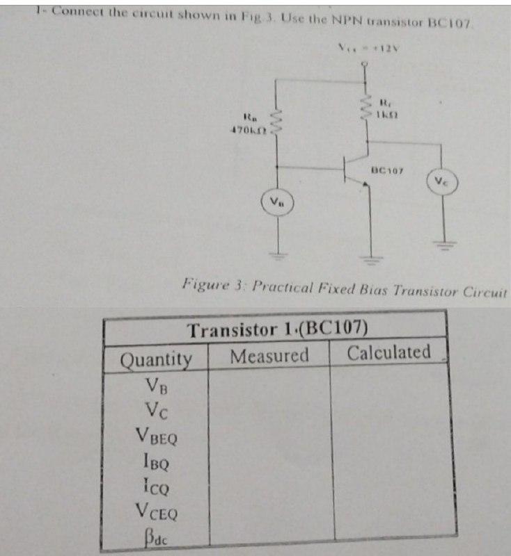
1- Connect the circuit shown in Fig. 3. Use the NPN transistor BC107 V. +12V Re 470k www VB R BC107 Ve Figure 3:

1- Connect the circuit shown in Fig. 3. Use the NPN transistor BC107 V. +12V Re 470k www VB R BC107 Ve Figure 3: Practical Fixed Bias Transistor Circuit Transistor 1.(BC107) Quantity VB Vc VBEQ IBQ ICQ VCEQ Bdc Measured Calculated
Step by Step Solution
3.52 Rating (155 Votes )
There are 3 Steps involved in it
Step: 1
To connect the circuit shown in Fig 3 with the NPN transistor BC107 follow these steps Power Supply ...
Get Instant Access to Expert-Tailored Solutions
See step-by-step solutions with expert insights and AI powered tools for academic success
Step: 2

Step: 3

Ace Your Homework with AI
Get the answers you need in no time with our AI-driven, step-by-step assistance
Get StartedRecommended Textbook for
Electric Machinery
Authors: Charles Kingsley, Jr, Stephen D. Umans
6th Edition
71230106, 9780073660097, 73660094, 978-0071230100
Students also viewed these Electrical Engineering questions
Question
Answered: 1 week ago
Question
Answered: 1 week ago
Question
Answered: 1 week ago
Question
Answered: 1 week ago
Question
Answered: 1 week ago
Question
Answered: 1 week ago
Question
Answered: 1 week ago
Question
Answered: 1 week ago
Question
Answered: 1 week ago
Question
Answered: 1 week ago
Question
Answered: 1 week ago
Question
Answered: 1 week ago
Question
Answered: 1 week ago
Question
Answered: 1 week ago
Question
Answered: 1 week ago
Question
Answered: 1 week ago
Question
Answered: 1 week ago
Question
Answered: 1 week ago
Question
Answered: 1 week ago
Question
Answered: 1 week ago
Question
Answered: 1 week ago
View Answer in SolutionInn App


