i need the ladder diagram and function chart
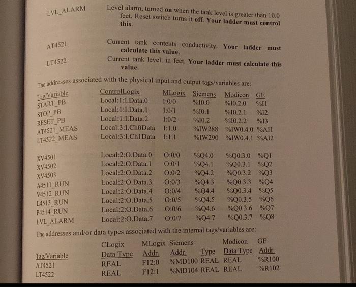
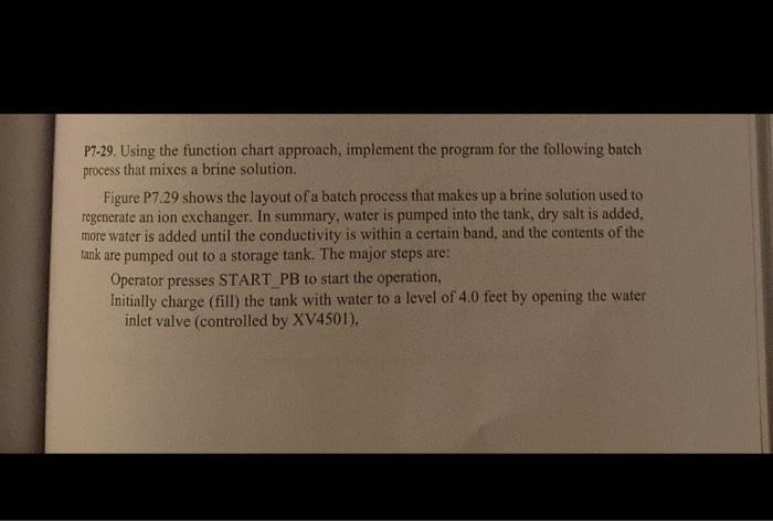
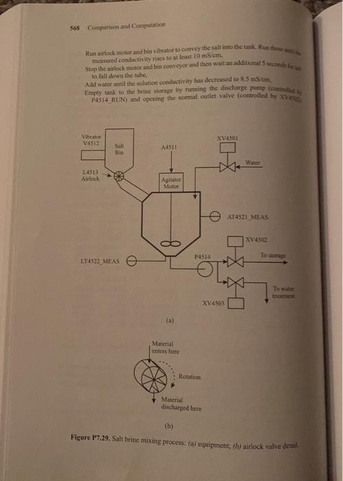
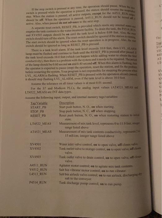
P7-29. Using the function chart approach, implement the program for the following batch process that mixes a brine solution. Figure P7.29 shows the layout of a batch process that makes up a brine solution used to regenerate an ion exchanger. In summary, water is pumped into the tank, dry salt is added, more water is added until the conductivity is within a certain band, and the contents of the tank are pumped out to a storage tank. The major steps are: Operator presses START PB to start the operation, Initially charge (fill) the tank with water to a level of 4.0 feet by opening the water inlet valve (controlled by XV4501). Run airlock motor and bin vibrator to convey the ralt into the tamk. Run these 2 in a measured condactihity rikes to at fead 10 mb. cm. to fall down the tabe, Add wader until the solntion conductivity has decreaiced 10.5.5mscm. (b) Figure P7.29. Salt brine mixing process: (a) equipment; (b) airlock valut detal If the stop switch is pressed at any time, the operation should paure. When ithe athy switch is peessed while the operation is patased, the station should resume the ruperiet step. When the-station is parsed, all active outputs. except for the A45II RIIN Cey should be off. When the operation is paused. A4511. RUN stroald not be tumat aff. If active. Also, when poused do not advance to the next step. A separate resct switch, RESET. PB, is provided which resets any internal stater and empties the tank contents to the water treatment facility. To drain the tank, the P.45/4 - 1/15 and XV4503 oufputs should be an until the tank level is below 0.08 feet Alcos the roe swich should ture off the alam. The reset switch should be ignored if the station is narin The start switch should be ignored when the reset operation is in progress. Alin, the rait switch shonld be ignored as long as RESET PB is pressed. There is a tank level alarm. If the tank: level excects 10.0 feet, then LVL. ALAPM. lamp mast be flashed and continue to flash until the RESET. PB is proseed after painet, if the tank level exceeds 10.0 feet (which can happen while adding water to ohtaiat the firil conductivity), then there is a problem with the system and it needs to be repaired. The feriod of the lamp should be 0.60 second on and 0.40 second off. When this alarm is flavhinge that the operator is expected to pause (stop) the operition, reset the station, and fix the problbefore restarting the system. Your program is not responsible for stopping the proces when 1.VL AL ARM is flashing. When RESET PB is pressed with the operation alricady paoset it sbould stop flashing LVL.AL.ARM. even if the tank level is above 100 feet. Assume the tolerance on all timer values is at most 0,01 second. For the S7 and Modicon PLCs, the analog input values (AT4S21 MEAS ant LT4522_-MEAS) are INT data types. Assume the following input, ostput, and intemial memory tags/variables: Aswme the tank is empty when the feveldrops beloa D.0s fect (apronimately I:0 inch). The ogeration does not repeat, After one briae welerioe hateh as pootoced. the kn airlock removes material from the bottom of the salt bin. An airlock allows material unteremoved from the bottorn of the bith, ats it is added at one lop of the bin. (Addition of msierul to the bin is not past of this problem.) Afs airlock coctiots of a sate notating inside a soninial cylinder (Figtire P7,29b). Material eaters from the top ints a wcige-thapcal dytiler, is conveyed to the bottom as the vaties rotate, and exts the bericm. The airlock haeler are similar to the wedge-shaped chambers of at Trivial Fursul panve piece that bulds toc Twedgies". The airlock is driven by a motor that is controlled by the L.4513 RUN wovt. When L4513. RUN is an, the airlock rotates, removing material from the bottom of the ha and plicing it in the chute. When L4513.RUN is off, no material is removed from. Bebortaiti of the bin. A whirator is nttached to the salt bin to kecp mnterial from ciampins so the sites ats it in Gishenged. The vibtator is driven by a motor that is coatrol cod by the N 4512 RUN output. 41 ese V4512. RUN is on, the vibrator motor totates. When V4512. RUN is off, the vibratoe molor is stopped. The vibrator must be run while the airlock motor is rutining. There are three valves in this system: 1. Water inlet yalve. When XV4501 is on, the valve is opened fo admit wafer into the tank. When XV4501 is off, the valve is slosed. 2. Tank outlet valve to storage. When XV4502 is on, the salve is opened to allow brine to be pumped into storage. When XV4502 is off, the ralie is clasel. 3. Tank outlet valve to drain. When XV4503 is on, the value is opened to allow brine to be purmped to the drain. When XV4503 is off, the salve is cloned. The P4514. RUN output controls the discharge pump. Wken P4514. RUN is on, the gump runs, when off, the ptimp is stopped. Enther XV45e2 ot XV4503 must also be ou (open valve) when running the puimp. The tank agitator is controlled by the A4511 RUN output. When A4511. RUM is on., the tank agitator is run; when A4511 RUN is off, the agitator is stopped, Ficecpt for the ititial charge of water, the agitator must be runming during all other steps. Theagitator muat bestcpped daring the antitial charge of Water. The tank level is measured by a level sensor attached to the bottom of the hank. The level sensor is calibrited to measure from 0 to 11 fect and is connccted to an analog input module having an ADC whose output integer (LT4522. MFAS) correspond to the lowest. and highest levels as specified before P717. The level meastirement value must be converted inlo uniss of feet and stured in the 1.T4522 internal memory location (a real riumber). The solution conductivity is measured by a sensor attached lo the side of the tank. The iensor is calibrated to measure from 2 to 15mS/cm (milli icmersecm) and is comected to 25 analog input module having an NDC whose output integer (ATAS21 MEAS) cecresponds to the lowest and highest conductivity as thocified betore P7-17. 1be: conductivity measurement value must be converted into units of m m/cm and stored in the AT 4521 internal memory locmtion (a real taumbet). LVL_ALARM Level alarm, turned on when the tank level is greater than 10.0 feet. Reset switch turns it off. Your ladder must control this. AT4521 Current tank contents conductivity. Your ladder must calculate this value. LT4522 Current tank level, in feet. Your ladder must calculate this value. Thandiresses associated with the physical input and output tags/variables are: The addresses and/or data types associated with the intermal tags/variables are: P7-29. Using the function chart approach, implement the program for the following batch process that mixes a brine solution. Figure P7.29 shows the layout of a batch process that makes up a brine solution used to regenerate an ion exchanger. In summary, water is pumped into the tank, dry salt is added, more water is added until the conductivity is within a certain band, and the contents of the tank are pumped out to a storage tank. The major steps are: Operator presses START PB to start the operation, Initially charge (fill) the tank with water to a level of 4.0 feet by opening the water inlet valve (controlled by XV4501). Run airlock motor and bin vibrator to convey the ralt into the tamk. Run these 2 in a measured condactihity rikes to at fead 10 mb. cm. to fall down the tabe, Add wader until the solntion conductivity has decreaiced 10.5.5mscm. (b) Figure P7.29. Salt brine mixing process: (a) equipment; (b) airlock valut detal If the stop switch is pressed at any time, the operation should paure. When ithe athy switch is peessed while the operation is patased, the station should resume the ruperiet step. When the-station is parsed, all active outputs. except for the A45II RIIN Cey should be off. When the operation is paused. A4511. RUN stroald not be tumat aff. If active. Also, when poused do not advance to the next step. A separate resct switch, RESET. PB, is provided which resets any internal stater and empties the tank contents to the water treatment facility. To drain the tank, the P.45/4 - 1/15 and XV4503 oufputs should be an until the tank level is below 0.08 feet Alcos the roe swich should ture off the alam. The reset switch should be ignored if the station is narin The start switch should be ignored when the reset operation is in progress. Alin, the rait switch shonld be ignored as long as RESET PB is pressed. There is a tank level alarm. If the tank: level excects 10.0 feet, then LVL. ALAPM. lamp mast be flashed and continue to flash until the RESET. PB is proseed after painet, if the tank level exceeds 10.0 feet (which can happen while adding water to ohtaiat the firil conductivity), then there is a problem with the system and it needs to be repaired. The feriod of the lamp should be 0.60 second on and 0.40 second off. When this alarm is flavhinge that the operator is expected to pause (stop) the operition, reset the station, and fix the problbefore restarting the system. Your program is not responsible for stopping the proces when 1.VL AL ARM is flashing. When RESET PB is pressed with the operation alricady paoset it sbould stop flashing LVL.AL.ARM. even if the tank level is above 100 feet. Assume the tolerance on all timer values is at most 0,01 second. For the S7 and Modicon PLCs, the analog input values (AT4S21 MEAS ant LT4522_-MEAS) are INT data types. Assume the following input, ostput, and intemial memory tags/variables: Aswme the tank is empty when the feveldrops beloa D.0s fect (apronimately I:0 inch). The ogeration does not repeat, After one briae welerioe hateh as pootoced. the kn airlock removes material from the bottom of the salt bin. An airlock allows material unteremoved from the bottorn of the bith, ats it is added at one lop of the bin. (Addition of msierul to the bin is not past of this problem.) Afs airlock coctiots of a sate notating inside a soninial cylinder (Figtire P7,29b). Material eaters from the top ints a wcige-thapcal dytiler, is conveyed to the bottom as the vaties rotate, and exts the bericm. The airlock haeler are similar to the wedge-shaped chambers of at Trivial Fursul panve piece that bulds toc Twedgies". The airlock is driven by a motor that is controlled by the L.4513 RUN wovt. When L4513. RUN is an, the airlock rotates, removing material from the bottom of the ha and plicing it in the chute. When L4513.RUN is off, no material is removed from. Bebortaiti of the bin. A whirator is nttached to the salt bin to kecp mnterial from ciampins so the sites ats it in Gishenged. The vibtator is driven by a motor that is coatrol cod by the N 4512 RUN output. 41 ese V4512. RUN is on, the vibrator motor totates. When V4512. RUN is off, the vibratoe molor is stopped. The vibrator must be run while the airlock motor is rutining. There are three valves in this system: 1. Water inlet yalve. When XV4501 is on, the valve is opened fo admit wafer into the tank. When XV4501 is off, the valve is slosed. 2. Tank outlet valve to storage. When XV4502 is on, the salve is opened to allow brine to be pumped into storage. When XV4502 is off, the ralie is clasel. 3. Tank outlet valve to drain. When XV4503 is on, the value is opened to allow brine to be purmped to the drain. When XV4503 is off, the salve is cloned. The P4514. RUN output controls the discharge pump. Wken P4514. RUN is on, the gump runs, when off, the ptimp is stopped. Enther XV45e2 ot XV4503 must also be ou (open valve) when running the puimp. The tank agitator is controlled by the A4511 RUN output. When A4511. RUM is on., the tank agitator is run; when A4511 RUN is off, the agitator is stopped, Ficecpt for the ititial charge of water, the agitator must be runming during all other steps. Theagitator muat bestcpped daring the antitial charge of Water. The tank level is measured by a level sensor attached to the bottom of the hank. The level sensor is calibrited to measure from 0 to 11 fect and is connccted to an analog input module having an ADC whose output integer (LT4522. MFAS) correspond to the lowest. and highest levels as specified before P717. The level meastirement value must be converted inlo uniss of feet and stured in the 1.T4522 internal memory location (a real riumber). The solution conductivity is measured by a sensor attached lo the side of the tank. The iensor is calibrated to measure from 2 to 15mS/cm (milli icmersecm) and is comected to 25 analog input module having an NDC whose output integer (ATAS21 MEAS) cecresponds to the lowest and highest conductivity as thocified betore P7-17. 1be: conductivity measurement value must be converted into units of m m/cm and stored in the AT 4521 internal memory locmtion (a real taumbet). LVL_ALARM Level alarm, turned on when the tank level is greater than 10.0 feet. Reset switch turns it off. Your ladder must control this. AT4521 Current tank contents conductivity. Your ladder must calculate this value. LT4522 Current tank level, in feet. Your ladder must calculate this value. Thandiresses associated with the physical input and output tags/variables are: The addresses and/or data types associated with the intermal tags/variables are
 i need the ladder diagram and function chart


