Answered step by step
Verified Expert Solution
Question
1 Approved Answer
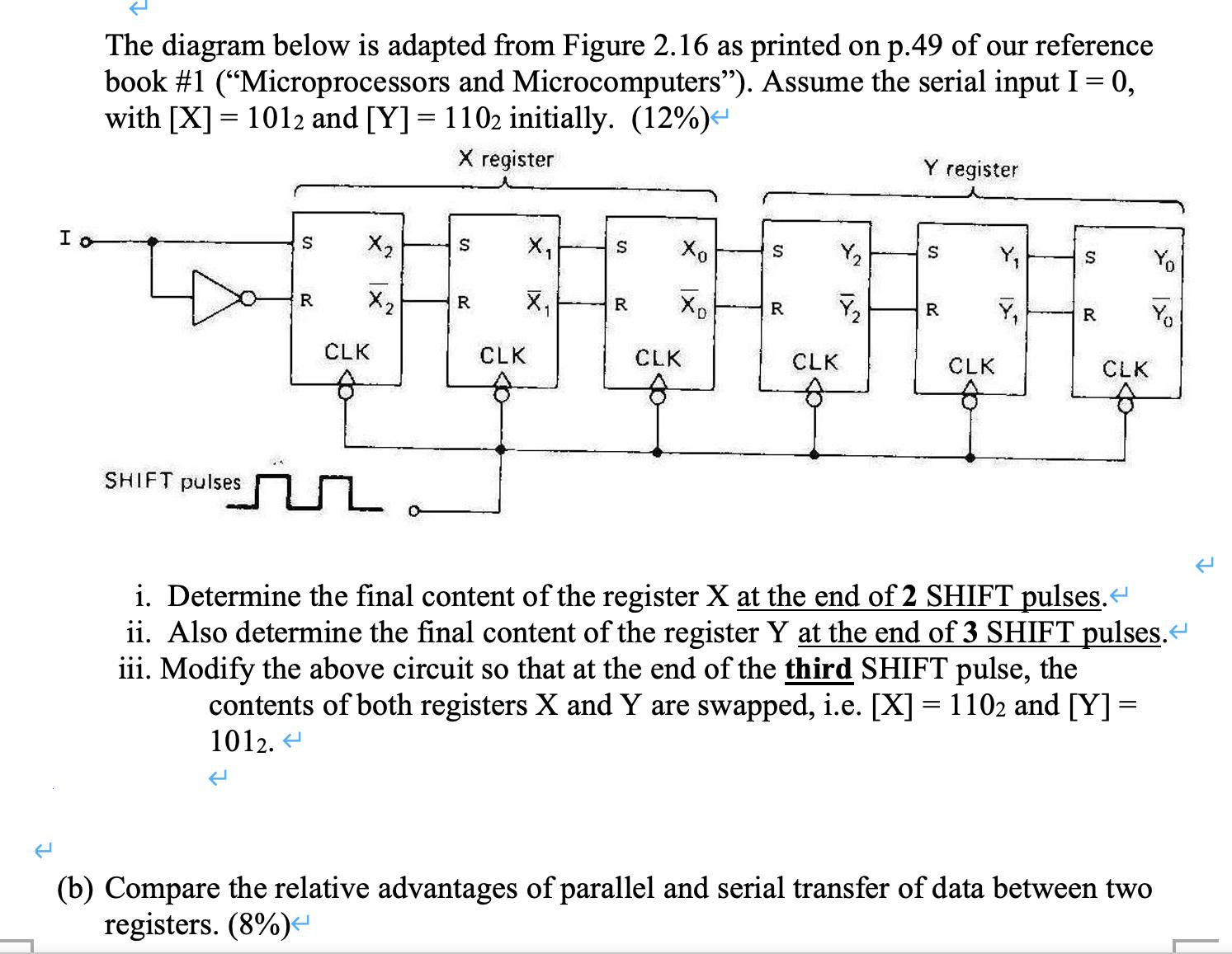
I o The diagram below is adapted from Figure 2.16 as printed on p.49 of our reference book #1 (Microprocessors and Microcomputers). Assume the

I o The diagram below is adapted from Figure 2.16 as printed on p.49 of our reference book #1 ("Microprocessors and Microcomputers"). Assume the serial input I = 0, with [X] = 1012 and [Y] = 1102 initially. (12%) < X register SHIFT pulses S R X X CLK S X 20 IX CLK S X X R Xo CLK S R Y CLK Y register S 20 CLK XI S R CLK Yo i. Determine the final content of the register X at the end of 2 SHIFT pulses. < ii. Also determine the final content of the register Y at the end of 3 SHIFT pulses. < iii. Modify the above circuit so that at the end of the third SHIFT pulse, the = contents of both registers X and Y are swapped, i.e. [X] = 1102 and [Y] = 1012. < (b) Compare the relative advantages of parallel and serial transfer of data between two registers. (8%) < K
Step by Step Solution
★★★★★
3.37 Rating (175 Votes )
There are 3 Steps involved in it
Step: 1
Answer Q2 a i Control input must be stable atleast f...
Get Instant Access to Expert-Tailored Solutions
See step-by-step solutions with expert insights and AI powered tools for academic success
Step: 2

Step: 3

Ace Your Homework with AI
Get the answers you need in no time with our AI-driven, step-by-step assistance
Get Started


