I post this question second time with all the needed information. Under you can find the needed tabel, all needed views off the building, and also an similar to this question example that my teacher did. I hope you can help me with this. 
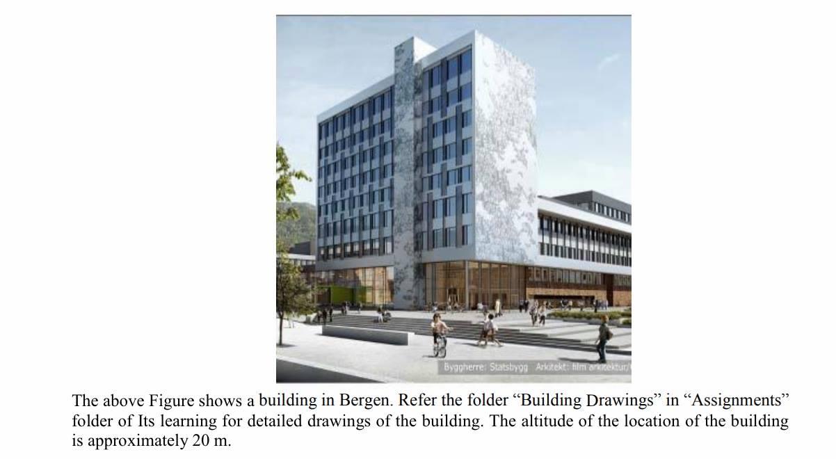
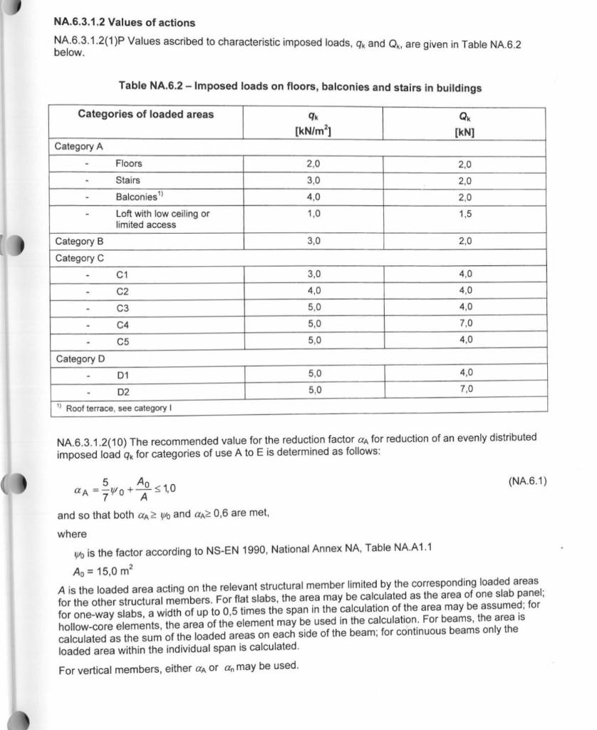
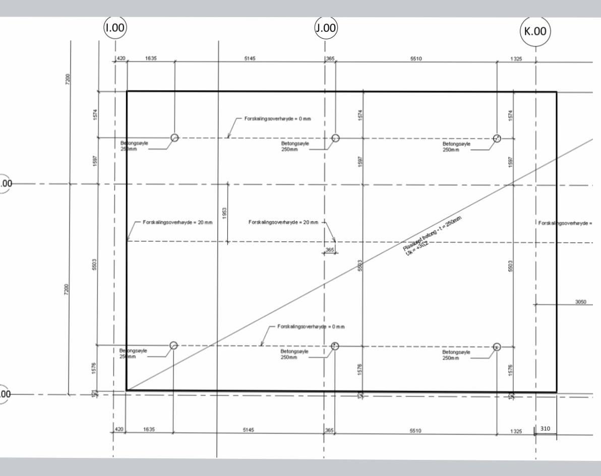
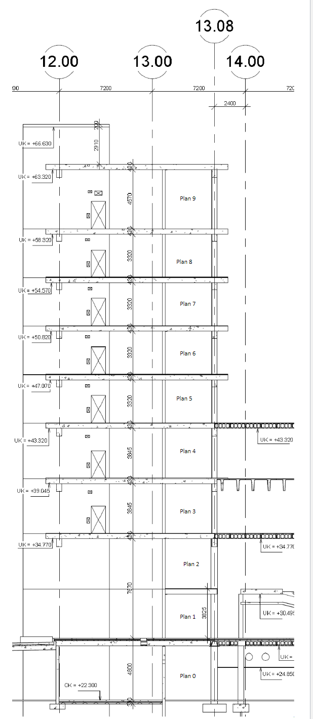
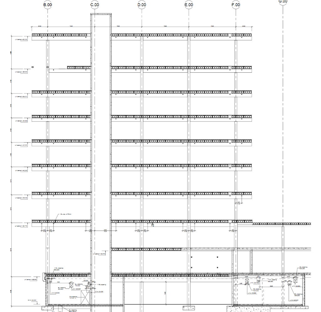
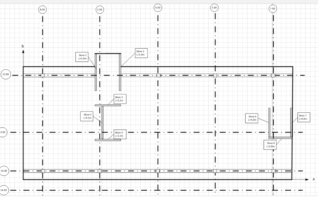
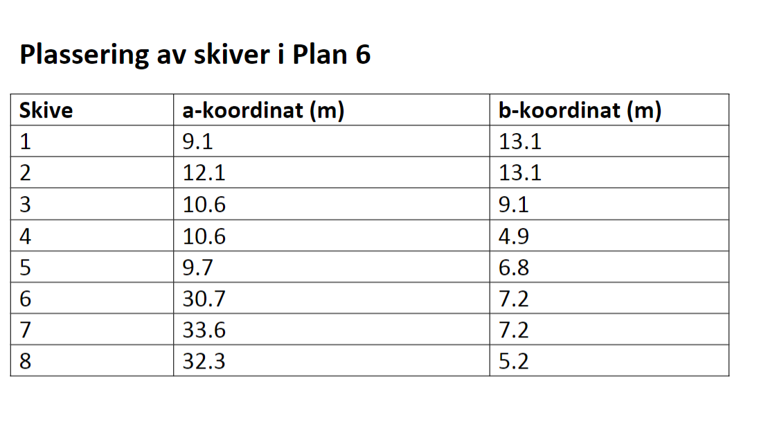
Question 2. English Calculate the design axial load for the column D0.0 / 12.0.0 located in floor 1 considering ultimate limit state. Self-weight of beams and columns must be taken into account in addition to the self-weight of floors. All beams are pre-cast elements and simply supported at both ends. The self-weight of the faade, porch and other plumbing cut-outs are considered as negligible. Byggherre: Statsbygg Arkitekt: Hilmanmektur The above Figure shows a building in Bergen. Refer the folder "Building Drawings in Assignments folder of Its learning for detailed drawings of the building. The altitude of the location of the building is approximately 20 m. NA.6.3.1.2 Values of actions NA.6.3.1.2(1)P Values ascribed to characteristic imposed loads, Gk and Qk, are given in Table NA.6.2 below. Table NA.6.2 - Imposed loads on floors, balconies and stairs in buildings Categories of loaded areas ak [kN/m] QK [kN] Category A Floors 2,0 2.0 Stairs 3,0 2.0 4,0 Balconies Loft with low ceiling or limited access 2,0 1,5 1,0 3,0 2.0 Category B Category C C1 3,0 4,0 4.0 C2 4,0 5,0 C3 4.0 C4 5,0 7,0 C5 5,0 4,0 Category D D1 4,0 5,0 5,0 D2 7,0 Roof terrace, see category 1 NA.6.3.1.2(10) The recommended value for the reduction factor aa for reduction of an evenly distributed imposed load Gk for categories of use A to E is determined as follows: 5 Vo + s 1.0 (NA.6.1) 7 A and so that both a2 yo and a 0,6 are met, where Vo is the factor according to NS-EN 1990, National Annex NA, Table NA.A1.1 A = 15,0 m2 A is the loaded area acting on the relevant structural member limited by the corresponding loaded areas for the other structural members. For flat slabs, the area may be calculated as the area of one slab panel: for one-way slabs, a width of up to 0,5 times the span in the calculation of the area may be assumed; for hollow-core elements, the area of the element may be used in the calculation. For beams, the area is calculated as the sum of the loaded areas on each side of the beam; for continuous beams only the loaded area within the individual span is calculated. For vertical members, either as or an may be used. 1.00 0.00 K.00 (420 1635 5145 1365 5510 1325 Forskalingsoverheyde 0 mm Bongsoyle 20 mm Betongseyle 250mm Betongseyle 250mm .00 Forskalingsoverhayde - 20 mm Forskalingsoverheyde - 20 mm + Forska goverheyde 365 Passot bolong-t250mm Uke 3050 Forskningsoverhede om | Bengseyle 25 mm Betongsayte 250mm Betongtayle 250 m 1 .00 SM 420 1635 5145 5510 1325 310 13.08 12.00 13.00 14.00 00 7200 7200 720 2400 all 012 UK = +66.630 10 o H UK = +63.320 | 4570 Plan 9 olan 9 - UK = +58 320 XI Plan 8 UK = +54.570 Plan 7 | UK = +50.8201 Plan 6 Plan 6 UK = +47.070 Plan 5 lan s ooooooooooooooooooo UK = +43 320 UK = +43.320 Plan 4 -49 UK = +39.045 Plan 3 10000000000000000000 UK = +34 770 UK = +34.770 Plan 2 UK = +30.49 Plan 1 Plan 1 VID BOOSAA UK = Plan 0 Plan o UK = +24.850 OK = +22 300 -- + -- BE - TEET) LINE 08 000BD0EED HTTERE. Drammos 11 11 ba 00000000000000000000000000 mum OOOO000000000 HIrt - - UUUTTOOTTOUD ETHI m m TORTUEnrrramm 00000000 nonm000 pm : Danonooooooooooooo ( DO'= 00's ooo 00' 009 0.00 E.00 B.00 1 b . - Skive 2 15.4m Skive L-5.4m 12.00 Skive 3 L-3.2m Skive (1) Skive 6 L-4.Om Skive 7 L-4.Om 3.00 - Skive 4 3.2m - Skive L-2.8m 13.08 - = 14.00 T 1 1 - 1 1 - Plassering av skiver i Plan 6 Skive 1 2 3 4 a-koordinat (m) 9.1 12.1 10.6 10.6 9.7 30.7. 33.6 32.3 b-koordinat (m) 13.1 13.1 9.1 4.9 6.8 7.2 7.2 5.2 5 6 7 8 Question 2. English Calculate the design axial load for the column D0.0 / 12.0.0 located in floor 1 considering ultimate limit state. Self-weight of beams and columns must be taken into account in addition to the self-weight of floors. All beams are pre-cast elements and simply supported at both ends. The self-weight of the faade, porch and other plumbing cut-outs are considered as negligible. Byggherre: Statsbygg Arkitekt: Hilmanmektur The above Figure shows a building in Bergen. Refer the folder "Building Drawings in Assignments folder of Its learning for detailed drawings of the building. The altitude of the location of the building is approximately 20 m. NA.6.3.1.2 Values of actions NA.6.3.1.2(1)P Values ascribed to characteristic imposed loads, Gk and Qk, are given in Table NA.6.2 below. Table NA.6.2 - Imposed loads on floors, balconies and stairs in buildings Categories of loaded areas ak [kN/m] QK [kN] Category A Floors 2,0 2.0 Stairs 3,0 2.0 4,0 Balconies Loft with low ceiling or limited access 2,0 1,5 1,0 3,0 2.0 Category B Category C C1 3,0 4,0 4.0 C2 4,0 5,0 C3 4.0 C4 5,0 7,0 C5 5,0 4,0 Category D D1 4,0 5,0 5,0 D2 7,0 Roof terrace, see category 1 NA.6.3.1.2(10) The recommended value for the reduction factor aa for reduction of an evenly distributed imposed load Gk for categories of use A to E is determined as follows: 5 Vo + s 1.0 (NA.6.1) 7 A and so that both a2 yo and a 0,6 are met, where Vo is the factor according to NS-EN 1990, National Annex NA, Table NA.A1.1 A = 15,0 m2 A is the loaded area acting on the relevant structural member limited by the corresponding loaded areas for the other structural members. For flat slabs, the area may be calculated as the area of one slab panel: for one-way slabs, a width of up to 0,5 times the span in the calculation of the area may be assumed; for hollow-core elements, the area of the element may be used in the calculation. For beams, the area is calculated as the sum of the loaded areas on each side of the beam; for continuous beams only the loaded area within the individual span is calculated. For vertical members, either as or an may be used. 1.00 0.00 K.00 (420 1635 5145 1365 5510 1325 Forskalingsoverheyde 0 mm Bongsoyle 20 mm Betongseyle 250mm Betongseyle 250mm .00 Forskalingsoverhayde - 20 mm Forskalingsoverheyde - 20 mm + Forska goverheyde 365 Passot bolong-t250mm Uke 3050 Forskningsoverhede om | Bengseyle 25 mm Betongsayte 250mm Betongtayle 250 m 1 .00 SM 420 1635 5145 5510 1325 310 13.08 12.00 13.00 14.00 00 7200 7200 720 2400 all 012 UK = +66.630 10 o H UK = +63.320 | 4570 Plan 9 olan 9 - UK = +58 320 XI Plan 8 UK = +54.570 Plan 7 | UK = +50.8201 Plan 6 Plan 6 UK = +47.070 Plan 5 lan s ooooooooooooooooooo UK = +43 320 UK = +43.320 Plan 4 -49 UK = +39.045 Plan 3 10000000000000000000 UK = +34 770 UK = +34.770 Plan 2 UK = +30.49 Plan 1 Plan 1 VID BOOSAA UK = Plan 0 Plan o UK = +24.850 OK = +22 300 -- + -- BE - TEET) LINE 08 000BD0EED HTTERE. Drammos 11 11 ba 00000000000000000000000000 mum OOOO000000000 HIrt - - UUUTTOOTTOUD ETHI m m TORTUEnrrramm 00000000 nonm000 pm : Danonooooooooooooo ( DO'= 00's ooo 00' 009 0.00 E.00 B.00 1 b . - Skive 2 15.4m Skive L-5.4m 12.00 Skive 3 L-3.2m Skive (1) Skive 6 L-4.Om Skive 7 L-4.Om 3.00 - Skive 4 3.2m - Skive L-2.8m 13.08 - = 14.00 T 1 1 - 1 1 - Plassering av skiver i Plan 6 Skive 1 2 3 4 a-koordinat (m) 9.1 12.1 10.6 10.6 9.7 30.7. 33.6 32.3 b-koordinat (m) 13.1 13.1 9.1 4.9 6.8 7.2 7.2 5.2 5 6 7 8


