

Question
I WANT A FULL VERILOG CODE using 3 procedural block (not just the explanation) please help... ` An-Najah National University Faculty of Engineering and Information
I WANT A FULL VERILOG CODE using 3 procedural block (not just the explanation)
please help...
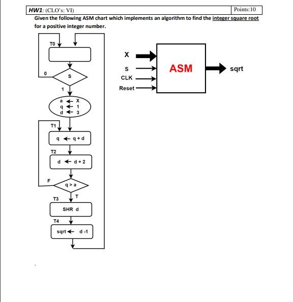
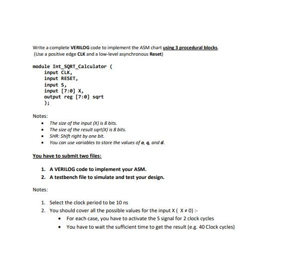
` An-Najah National University Faculty of Engineering and Information Technology Computer Engineering Department Digital Circuit Design II (10636321) Final Assignment Due to : 24/12/2022 HW1: (CLOs: VI) Points:10 Given the following ASM chart which implements an algorithm to find the integer square root for a positive integer number. ` Write a complete VERILOG code to implement the ASM chart using 3 procedural blocks. (Use a positive edge CLK and a low-level asynchronous Reset) module Int_SQRT_Calculator ( input CLK, input RESET, input S, input [7:0] X, output reg [7:0] sqrt ); Notes: The size of the input (X) is 8 bits. The size of the result sqrt(X) is 8 bits. SHR: Shift right by one bit. You can use variables to store the values of a, q, and d. You have to submit two files: 1. A VERILOG code to implement your ASM. 2. A testbench file to simulate and test your design. Notes: 1. Select the clock period to be 10 ns 2. You should cover all the possible values for the input X ( X 0) :- For each case, you have to activate the S signal for 2 clock cycles You have to wait the sufficient time to get the result (e.g. 40 Clock cycles)
Step by Step Solution
There are 3 Steps involved in it
Step: 1

Get Instant Access to Expert-Tailored Solutions
See step-by-step solutions with expert insights and AI powered tools for academic success
Step: 2

Step: 3
Ace Your Homework with AI
Get the answers you need in no time with our AI-driven, step-by-step assistance
Get Started
Mastering Real Time Analytics In Big Data A Comprehensive Guide For Everyone
Authors: Lennox Mark
1st Edition
B0CPTC9LY9, 979-8869045706