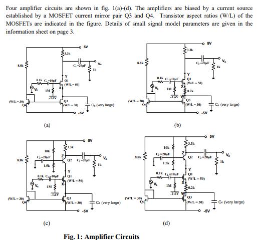
Four amplifier circuits are shown in fig. 1(a)-(d). The amplifiers are biased by a current source established by a MOSFET current mirror pair Q3

Four amplifier circuits are shown in fig. 1(a)-(d). The amplifiers are biased by a current source established by a MOSFET current mirror pair Q3 and Q4. Transistor aspect ratios (W/L) of the MOSFETs are indicated in the figure. Details of small signal model parameters are given in the information sheet on page 3. 8.8k (W/L-30) 04 8.8k (W/L.-30) 04 Blk C wh IM w -LAV 10k C-20F 1.5k 0.1k C10F w IM O X 23.3k For -0 5V C-0 01 (WL-50) X 03 kW-30) 3.3k -SV - SV 02 C-20 Y OL (W/L-50) 03 W-30) O-SV 1k C, (very large) V Fu Ik V Ci (very large) 8.8k (WA.-30) 04 8.8k (W/L=30) 04 Fig. 1: Amplifier Circuits alk C V IM 10k G20 F 'V 1.5k TSV W 8.lk C1F w IM (d) (b) 3.3k Y 01 (WL-50) 23.3k - 5V 20.2k 03 (WL-30) X wit G-20 -0-5V 0.2k 02 G-20F Y QI (W/L-50) Q3 (W/L=30) -O-SV 5V C (very large) V T V Ci (very large)
Step by Step Solution
There are 3 Steps involved in it
Step: 1
V 6V Load current unregulated input I ...
See step-by-step solutions with expert insights and AI powered tools for academic success
Step: 2

Step: 3

Ace Your Homework with AI
Get the answers you need in no time with our AI-driven, step-by-step assistance
Get Started


