If you don't know the correct solution to the problem, please don't take the question. If possible, write the solution on paper. Thank you in advance.


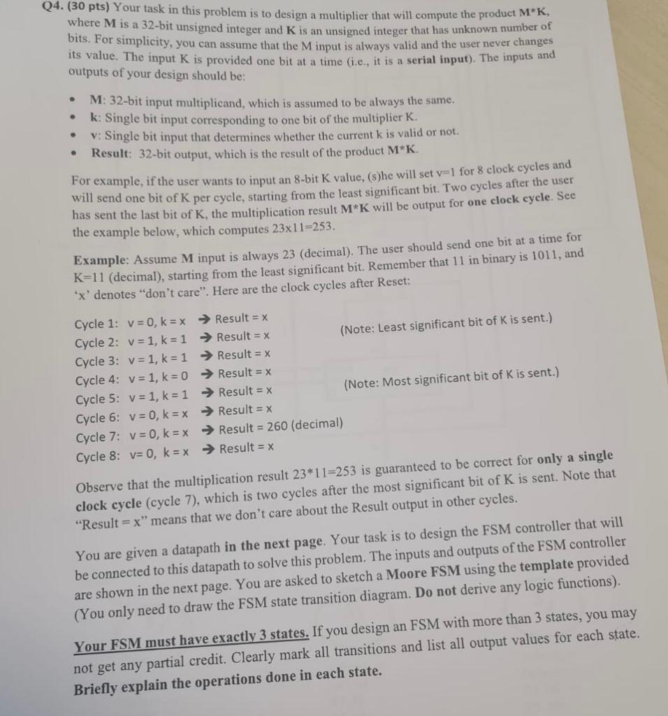
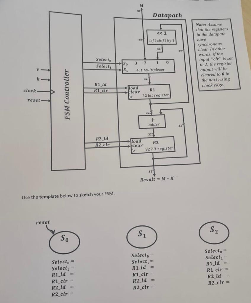
(30 pts) Your task in this problem is to design a multiplier that will compute the product MK, where M is a 32 -bit unsigned integer and K is an unsigned integer that has unknown number of bits. For simplicity, you can assume that the M input is always valid and the user never changes its value. The input K is provided one bit at a time (i.e., it is a serial input). The inputs and outputs of your design should be: - M: 32-bit input multiplicand, which is assumed to be always the same. - k: Single bit input corresponding to one bit of the multiplier K. - v: Single bit input that determines whether the current k is valid or not. - Result: 32-bit output, which is the result of the product MK. For example, if the user wants to input an 8-bit K value, (s)he will set v=1 for 8 clock cycles and will send one bit of K per cycle, starting from the least significant bit. Two cycles after the user has sent the last bit of K, the multiplication result MK will be output for one clock cycle. See the example below, which computes 2311=253. Example: Assume M input is always 23 (decimal). The user should send one bit at a time for K=11 (decimal), starting from the least significant bit. Remember that 11 in binary is 1011 , and ' x ' denotes "don't care". Here are the clock cycles after Reset: Cycle 1: v=0,k=x Result =x Cycle 2: v=1,k=1 Result =x (Note: Least significant bit of K is sent.) Cycle 3: v=1,k=1 Result =x Cycle 4: v=1,k=0 Result =x Cycle 5: v=1,k=1 Result =x (Note: Most significant bit of K is sent.) Cycle 6: v=0,k=x Result =x Cycle 7: v=0,k=x Result =260 (decimal) Cycle 8: v=0,k=x Result =x Observe that the multiplication result 2311=253 is guaranteed to be correct for only a single clock cycle (cycle 7), which is two cycles after the most significant bit of K is sent. Note that "Result =x " means that we don't care about the Result output in other cycles. You are given a datapath in the next page. Your task is to design the FSM controller that wil be connected to this datapath to solve this problem. The inputs and outputs of the FSM controlle are shown in the next page. You are asked to sketch a Moore FSM using the template provide (You only need to draw the FSM state transition diagram. Do not derive any logic functions). Your FSM must have exactly 3 states. If you design an FSM with more than 3 states, you n not get any partial credit. Clearly mark all transitions and list all output values for each st Briefly explain the operations done in each state. Use the template below to sketch your FSM


