Question
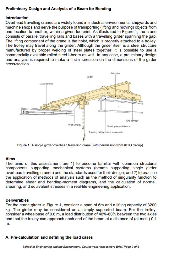
Image transcription text Preliminary Design and Analysis of a Beam for Bending Introduction Overhead travelling cranes are widely found in industrial environments, shipyards and machine

Image transcription text
Preliminary Design and Analysis of a Beam for Bending Introduction Overhead travelling cranes arewidely found in industrial environments, shipyards and machine shops and serve the purpose of
transporting (lifting and moving) objects from one location to another, within a given footpri...

Image transcription text
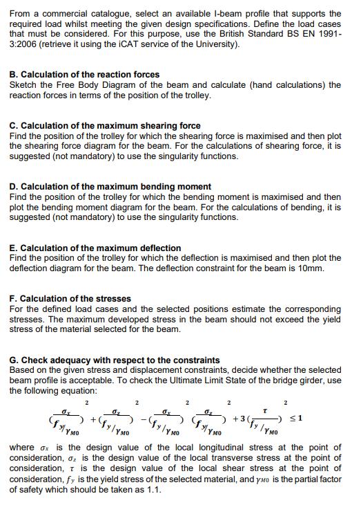
From a commercial catalogue, select an available I-beam profile that supports the required load whilstmeeting the given design specifications. Define the load cases that must be considered. For this
purpose, use the British Standard BS EN 1991- 3:2006 (retrieve it using the iCAT service o...
A. Pre-calculation and defining the load cases
School of Engineering and the Environment. Coursework Assessment Brief. Page 4 of 5
From a commercial catalogue, select an available I-beam profile that supports the
required load whilst meeting the given design specifications. Define the load cases
that must be considered. For this purpose, use the British Standard BS EN 1991-
3:2006
E. Calculation of the maximum deflection
Find the position of the trolley for which the deflection is maximised and then plot the
deflection diagram for the beam. The deflection constraint for the beam is 10mm.
F. Calculation of the stresses
For the defined load cases and the selected positions estimate the corresponding
stresses. The maximum developed stress in the beam should not exceed the yield
stress of the material selected for the beam.
G. Check adequacy with respect to the constraints
Based on the given stress and displacement constraints, decide whether the selected
beam profile is acceptable. To check the Ultimate Limit State of the bridge girder, use
the following equation:
????
????????
(???????? )
⁄????????????
????
????????
+ (???????? )
⁄????????????
????
????????
− (???????? )
⁄????????????
????
????????
(???????? )
⁄????????????
????
????
+ ???? (????????
)
⁄????????????
≤ ????
where ???????? is the design value of the local longitudinal stress at the point of
consideration, ???????? is the design value of the local transverse stress at the point of
consideration, ???? is the design value of the local shear stress at the point of
consideration, ???????? is the yield stress of the selected material, and ????????0 is the partial factor
of safety which should be taken as 1.1.
H. Conclusions and recommendations
Interpret the findings, draw conclusions, and make recommendations
Preliminary Design and Analysis of a Beam for Bending Introduction Overhead travelling cranes are widely found in industrial environments, shipyards and machine shops and serve the purpose of transporting (lifting and moving) objects from one location to another, within a given footprint. As illustrated in Figure 1, the crane consists of parallel travelling rails and bases with a travelling girder spanning the gap. The lifting component of the crane is the hoist, which is properly attached to a trolley. The trolley may travel along the girder. Although the girder itself is a steel structure manufactured by proper welding of steel plates together, it is possible to use a commercially available rolled steel I-beam as well. In any case, a preliminary design and analysis is required to make a first impression on the dimensions of the girder cross-section. Side roller Gerdar Geared motor End carriage Hoist & trolley Traveling base H-beam) Traveling rail (ght rail or square rai Figure 1: A single girder overhead travelling crane (with permission from KITO Group). Aims The aims of this assessment are 1) to become familiar with common structural components supporting mechanical systems (beams supporting single girder overhead travelling cranes) and the standards used for their design; and 2) to practice the application of methods of analysis such as the method of singularity function to determine shear and bending-moment diagrams, and the calculation of normal, shearing, and equivalent stresses in a real-life engineering application. Deliverables For the crane girder in Figure 1, consider a span of 6m and a lifting capacity of 3200 kg. The girder may be considered as a simply supported beam. For the trolley, consider a wheelbase of 0.6 m, a load distribution of 40%-60% between the two axles and that the trolley can approach each end of the beam at a distance of (at most) 0.1 m. A. Pre-calculation and defining the load cases School of Engineering and the Environment. Coursework Assessment Brief. Page 3 of 5
Step by Step Solution
There are 3 Steps involved in it
Step: 1

Get Instant Access to Expert-Tailored Solutions
See step-by-step solutions with expert insights and AI powered tools for academic success
Step: 2

Step: 3

Ace Your Homework with AI
Get the answers you need in no time with our AI-driven, step-by-step assistance
Get Started


