Question
Image transcription text Using the deadboltsubassemblyrom APPG04, createa multiview layout drawingof the subassemblyith the overall (maximum) HWD dimensionedThen createa layoutdrawing of the Right_Side_PaneAssumethe panelis modifiedfrom

Image transcription text
Using the deadboltsubassemblyrom APPG04, createa multiview layout drawingof the subassemblyith the overall (maximum) HWD dimensionedThen
createa layoutdrawing of the Right_Side_PaneAssumethe panelis modifiedfrom a standardpartthatis a squarepiece of MDF. Youwill needto
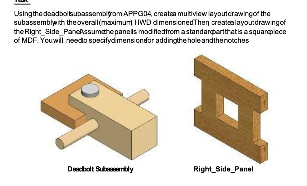
specifydimensionsfor addingthe hole and the notches S Deadbolt Subassembly Right_Side_Panel
Using the deadboltsubassemblyrom APPG04, createa multiview layout drawingof the subassemblyith the overall (maximum) HWD dimensionedThen createa layoutdrawing of the Right_Side_PaneAssumethe panelis modifiedfrom a standardpartthatis a squarepiece of MDF. Youwill needto specifydimensionsfor addingthe hole and the notches S Deadbolt Subassembly Right_Side_Panel
Using the deadboltsubassemblfrom APPG04, createa multiview layoutdrawingof the subassemblwith the overall (maximum) HWD dimensioned Then createa layout drawingof the Right Side_PaneAssumethepanelis modified from a standardart that is a squarepiece of MDF. You will needto specifydimensions for addingthe hole and the notches Deadbolt Subassembly A Right Side_Panel
Step by Step Solution
There are 3 Steps involved in it
Step: 1

Get Instant Access to Expert-Tailored Solutions
See step-by-step solutions with expert insights and AI powered tools for academic success
Step: 2

Step: 3

Ace Your Homework with AI
Get the answers you need in no time with our AI-driven, step-by-step assistance
Get Started


