Answered step by step
Verified Expert Solution
Question
1 Approved Answer
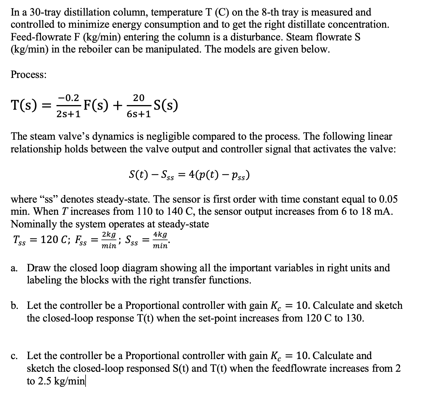
In a 3 0 - tray distillation column, temperature T ( C ) on the 8 - th tray is measured and controlled to minimize
In a tray distillation column, temperature on the th tray is measured and
controlled to minimize energy consumption and to get the right distillate concentration.
Feedflowrate entering the column is a disturbance. Steam flowrate
in the reboiler can be manipulated. The models are given below.
Process:
The steam valve's dynamics is negligible compared to the process. The following linear
relationship holds between the valve output and controller signal that activates the valve:
where ss denotes steadystate. The sensor is first order with time constant equal to
min. When increases from to the sensor output increases from to
Nominally the system operates at steadystate
;;
a Draw the closed loop diagram showing all the important variables in right units and
labeling the blocks with the right transfer functions.
b Let the controller be a Proportional controller with gain Calculate and sketch
the closedloop response when the setpoint increases from to
c Let the controller be a Proportional controller with gain Calculate and
sketch the closedloop responsed and when the feedflowrate increases from
to inIn a tray distillation column, temperature T C on the th tray is measured and controlled to minimize energy consumption and to get the right distillate concentration. Feedflowrate F kgmin entering the column is a disturbance. Steam flowrate S kgmin in the reboiler can be manipulated. The models are given below.
Process:
Tss Fss Ss
The steam valves dynamics is negligible compared to the process. The following linear relationship holds between the valve output and controller signal that activates the valve:
StSssptpss
where ss denotes steadystate. The sensor is first order with time constant equal to min. When T increases from to C the sensor output increases from to mA Nominally the system operates at steadystate: Tss C; Fsskgmin; Ssskgmin
Draw the closed loop diagram showing all the important variables in right units and labeling the blocks with the right transfer functions.
Let the controller be a Proportional controller with gain Kc Calculate and sketch the closedloop response Tt when the setpoint increases from C to
Let the controller be a Proportional controller with gain Kc Calculate and sketch the closedloop responsed St and Tt when the feedflowrate increases from to kgmin

Step by Step Solution
There are 3 Steps involved in it
Step: 1

Get Instant Access to Expert-Tailored Solutions
See step-by-step solutions with expert insights and AI powered tools for academic success
Step: 2

Step: 3

Ace Your Homework with AI
Get the answers you need in no time with our AI-driven, step-by-step assistance
Get Started


