Answered step by step
Verified Expert Solution
Question
1 Approved Answer
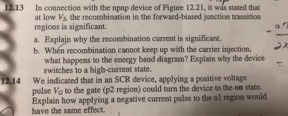
12.13 In connection with the npnp device of Figure 12.21, it was stated that at low Vs, the recombination in the forward-biased junction transition


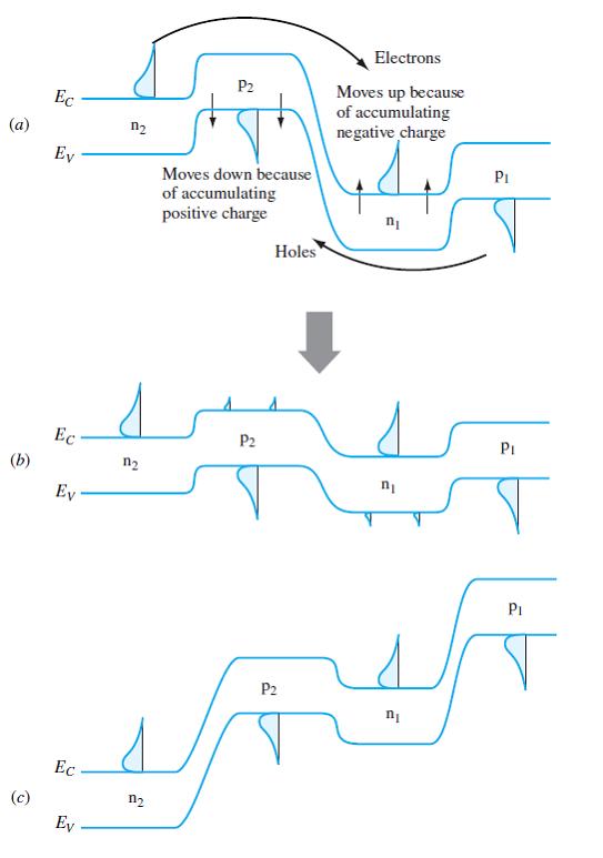
12.13 In connection with the npnp device of Figure 12.21, it was stated that at low Vs, the recombination in the forward-biased junction transition regions is significant. a. Explain why the recombination current is significant. b. When recombination cannot keep up with the carrier injection, what happens to the energy band diagram? Explain why the device switches to a high-current state. 12.14 We indicated that in an SCR device, applying a positive voltage pulse VG to the gate (p2 region) could turn the device to the on state. Explain how applying a negative current pulse to the nl region would have the same effect. (a) (b) (c) Ec Ey Ec Ev Ec Ev 2 n s n 2 2 n P2 Moves down because of accumulating positive charge P2 Holes P2 Electrons Moves up because of accumulating negative charge n n P PI PI 12.13 In connection with the npnp device of Figure 12.21, it was stated that at low Vs, the recombination in the forward-biased junction transition regions is significant. a. Explain why the recombination current is significant. b. When recombination cannot keep up with the carrier injection, what happens to the energy band diagram? Explain why the device switches to a high-current state. 12.14 We indicated that in an SCR device, applying a positive voltage pulse VG to the gate (p2 region) could turn the device to the on state. Explain how applying a negative current pulse to the nl region would have the same effect. (a) (b) (c) Ec Ey Ec Ev Ec Ev 2 n s n 2 2 n P2 Moves down because of accumulating positive charge P2 Holes P2 Electrons Moves up because of accumulating negative charge n n P PI PI
Step by Step Solution
★★★★★
3.52 Rating (172 Votes )
There are 3 Steps involved in it
Step: 1
charge in dol these holes in 1 layer reduce the we m layer of deplection region these leads to reduc...
Get Instant Access to Expert-Tailored Solutions
See step-by-step solutions with expert insights and AI powered tools for academic success
Step: 2

Step: 3

Ace Your Homework with AI
Get the answers you need in no time with our AI-driven, step-by-step assistance
Get Started


