 In MATLAB


 For york id use 215026388
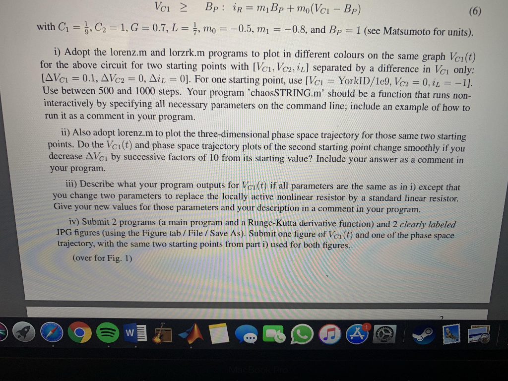
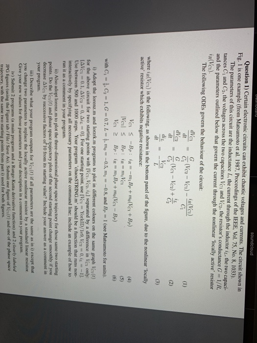
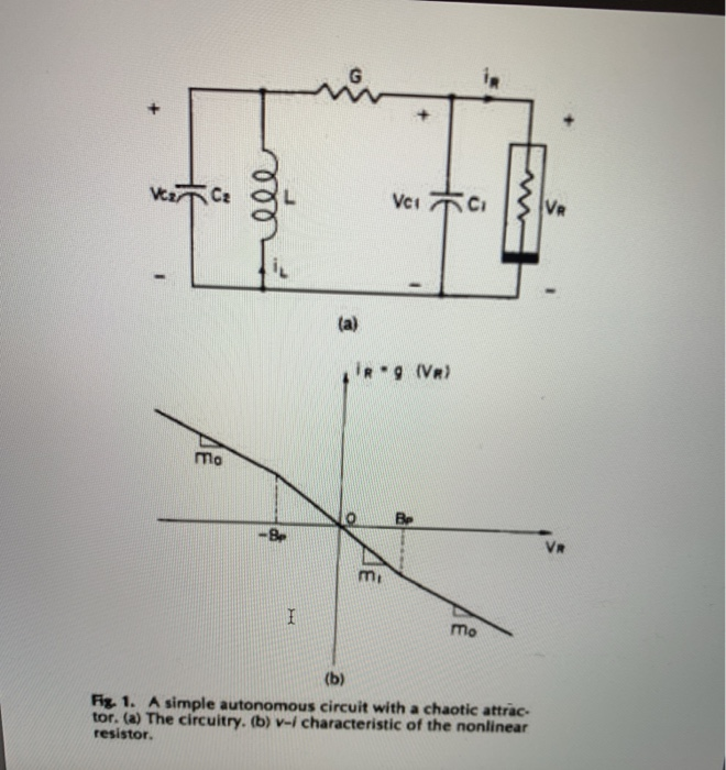
with C1 = 1 , C,-1, G = 07, L = , mo0.5, m,--0.8, and BP = 1 (see Matsumoto for units) . i) Adopt the lorenz.m and lorzrk.m programs to plot in different colours on the same graph Vci(t) for the above circuit for two starting points with Vei. Vc2, iII separated by a difference in Vei only: AVel 0.1, Ve,-0, L 0]. For one starting point, use [Ve,-YorkID/1e9,Vc2-0, il :-1]. Use between 500 and 1000 steps. Your program 'chaosSTRING.m should be a function that runs non- interactively by specifying all necessary parameters on the command line; include an example of how to run it as a comment in your program ii) Also adopt lorenz.m to plot the three-dimensional phase space trajectory for those same two starting points. Do the Vci(t) and phase space trajectory plots of the second starting point change smoothly if you decrease 1 by successive factors of 10 from its starting value? Include your answer as a comment in your program. ii) Describe what your program outputs for Ve () if all parameters are the same as in i) except that you change two parameters to replace the locally active nonlinear resistor by a standard linear resistor Give your new values for those parameters and your description in a comment in your program. iv) Submit 2 programs (a main program and a Runge-Kutta derivative function) and 2 clearly labeled JPG figures (using the Figure tab/ File /Save As). Submit one figure of Ver ( and one of the phase space trajectory, with the same two starting points from part i) used for both figures. (over for Fig. 1) Question 1) Certain electronic circuits can exhibit chaotic voltages and currents. The circuit shown in Fig. 1 is one example (from Matsumoto et al. 1987, Proceedings of the IEEE, Vol. 75, No. 8, 1033). The parameters of this circuit are the inductance L, the current through the inductor iz. the two capaci- tances C and C2, the voltages across the two capacitors Ver and Vcz. the resistor's conductance G - 1/R, and the parameters outlined below that govern the current through the nonlinear locally active resistor The following ODEs govern the behaviour of the circuit: where iR(Vca) is the following, as shown in the bottom panel of the figure, due to the nonlinear locally active' resistor which exhibits negative resistance: with Ci-l, G-1, G = 0.7, L-, mo--0.5, mi--08, and BP = 1 (see Matsumoto for units). i) Adopt the lorenz.m and lorzrk.m programs to plot in different colours on the same graph Vert) for the above circuit for two starting points with [Vor, Vez,i] separated by a difference in Ver only: [AVel 0.1. 'c2 0, 1 0]. For one starting point, use [Ver.-York!D/1e9. Vc 0, i1--1]. Use between 500 and 1000 steps. Your program 'chaos STRING.m' should be a function that runs non- interactively by specifying all necessary parameters on the command line: include an example of how to run it as a comment in your program ii) Also adopt lorenz.m to plot the three-dimensional phase space trajectory for those same two starting points. Do the Vea(t) and phase space trajectory plots of the second starting point change smoothly if you decrease AVei by successive factors of 10 from its starting value? Include your answer as a comment itn your program. iii) Describe what your program outputs for Vos(t) if all parameters are the same as in i) except that you change two parameters to replace the locally active nonlinear resistor by a standard linear resistor Give your new values for those parameters and your description in a comment in your program. iv) Submit 2 programs (a main program and a Runge-Kutta derivative function) and 2 clearly labeled JPG figures (using the Figure tab/File /Save As). Submit one figure of Ver(t) and one of the phase space trajectory, with the same two starting points from part i) used for both figures mo Be - Be Va mi mo Fiz. 1. A simple autonomous circuit with a chaotic attrac- tor. (a) The circuitry. resistor. v-, characteristic of the nonlinear 19 lines (16 sloc) 485 Bytes 1 function deriv -lorzrk (s,t,param) 2%Returns right-hand side of Lorenz model ODEs % Inputs State vector [x y z] Time (not used) 6 % param Parameters [r sigma b] 7 % Output 8deriv Derivatives [dx/dt dy/dt dz/dt] 10 For clarity, unravel input vectors 11 xs(1); ys (2): zs(3): param ( 1 ) ; param ( 2 ) ; r# sigma b param(3); - 13 14 %* Return the derivatives [dx/dt dy/dt dz/dt] 15 deriv(1) sigma*(y-x) 1.6 deriv(2) -r*x y x*z; - - 17 deriv(3)ey-bez 18 return 4 lines (45 sloc) 1.87 KB % lorenz -Program to compute the trajectories of the Lorenz 2 % equations using the adaptive Runge-Kutta method. 3 clear; help lorenz; 4 5 %% * Set initial state x,y,z and parameters r, sigma, b 6 state = input ('Enter the initial position [x y z]: ; 7 r input( Enter the parameter r 8 sigma = 10"; % Parameter sigma b 8./3. ; % Parameter b param [r sigma b]; % vector of parameters passed to rka 11 tau 1; 12 err 1.e-3; % Initial guess for the timestep % Error tolerance 13 14 %% * Loop over the desired number of steps 15 time -0 16 nstep nput( 'Enter number of steps : '); 17 for istep-1: nstep 18 19 %* Record values for plotting 20state(1); y - state(2): z state(3); 21 tplot(istep) -time; tauplot(istep) tau; if rem(istep,50)
 In MATLAB


 For york id use 215026388


