Answered step by step
Verified Expert Solution
Question
1 Approved Answer
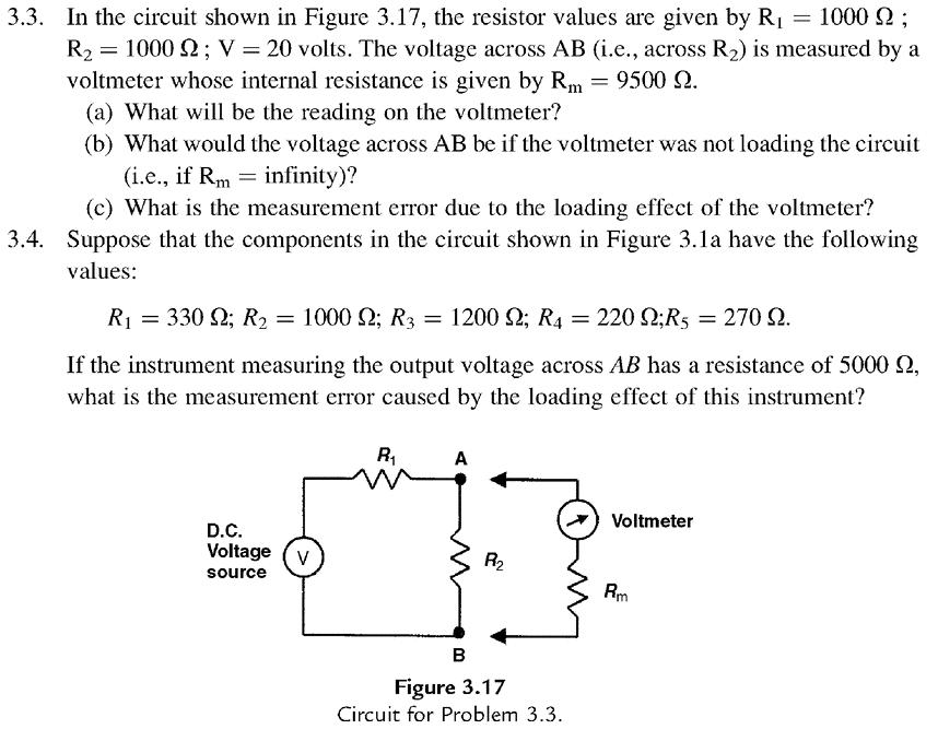
3.3. In the circuit shown in Figure 3.17, the resistor values are given by R1 = 1000 2 ; R2 = 1000 2; V

3.3. In the circuit shown in Figure 3.17, the resistor values are given by R1 = 1000 2 ; R2 = 1000 2; V 20 volts. The voltage across AB (i.e., across R2) is measured by a voltmeter whose internal resistance is given by Rm 9500 2. (a) What will be the reading on the voltmeter? (b) What would the voltage across AB be if the voltmeter was not loading the circuit (i.e., if Rm = infinity)? (c) What is the measurement error due to the loading effect of the voltmeter? 3.4. Suppose that the components in the circuit shown in Figure 3.1a have the following values: R1 = 330 2; R2 = 1000 2; R3 = 1200 2; R4 = 220 2;R5 = 270 2. If the instrument measuring the output voltage across AB has a resistance of 5000 2, what is the measurement error caused by the loading effect of this instrument? R, A Voltmeter D.C. Voltage (v R2 source Rm Figure 3.17 Circuit for Problem 3.3.
Step by Step Solution
★★★★★
3.47 Rating (167 Votes )
There are 3 Steps involved in it
Step: 1

Get Instant Access to Expert-Tailored Solutions
See step-by-step solutions with expert insights and AI powered tools for academic success
Step: 2

Step: 3

Ace Your Homework with AI
Get the answers you need in no time with our AI-driven, step-by-step assistance
Get Started


