Question
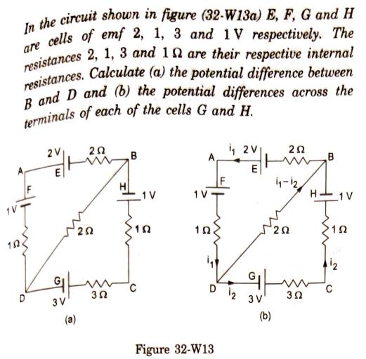
In the circuit shown in figure (32-W13a) E, F, G and H are cells of emf 2, 1, 3 and 1V respectively. The resistances

In the circuit shown in figure (32-W13a) E, F, G and H are cells of emf 2, 1, 3 and 1V respectively. The resistances 2, 1, 3 and 19 are their respective internal resistances. Calculate (a) the potential difference between B and D and (b) the potential differences across the terminals of each of the cells G and H. 2V E G 252 202 3V 3 B 1 V 102 C 152. Figure 32-W13 2V E 12 3 V (b) 202 1-12 202 352 B 1 V 152 2
Step by Step Solution
3.42 Rating (158 Votes )
There are 3 Steps involved in it
Step: 1
The detailed ...
Get Instant Access to Expert-Tailored Solutions
See step-by-step solutions with expert insights and AI powered tools for academic success
Step: 2

Step: 3

Ace Your Homework with AI
Get the answers you need in no time with our AI-driven, step-by-step assistance
Get StartedRecommended Textbook for
Applied Physics
Authors: Dale ewen, Neill schurter, P. erik gundersen
10th Edition
978-0136116332, 136116337, 9780132830096, 978-0132109277
Students also viewed these Physics questions
Question
Answered: 1 week ago
Question
Answered: 1 week ago
Question
Answered: 1 week ago
Question
Answered: 1 week ago
Question
Answered: 1 week ago
Question
Answered: 1 week ago
Question
Answered: 1 week ago
Question
Answered: 1 week ago
Question
Answered: 1 week ago
Question
Answered: 1 week ago
Question
Answered: 1 week ago
Question
Answered: 1 week ago
Question
Answered: 1 week ago
Question
Answered: 1 week ago
Question
Answered: 1 week ago
Question
Answered: 1 week ago
Question
Answered: 1 week ago
Question
Answered: 1 week ago
Question
Answered: 1 week ago
Question
Answered: 1 week ago
Question
Answered: 1 week ago
View Answer in SolutionInn App


