In the following questions, you will design the circuit of the Tickle Me Elmo...
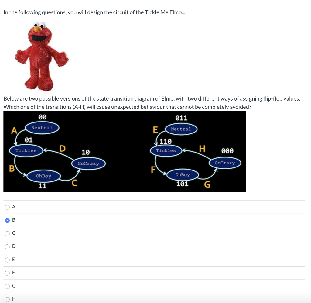
(1) Below are two possible versions of the state transition diagram of Elmo, with two different ways of assigning flip-flop values. Which one of the transitions (A-H) will cause unexpected behaviour that cannot be completely avoided?

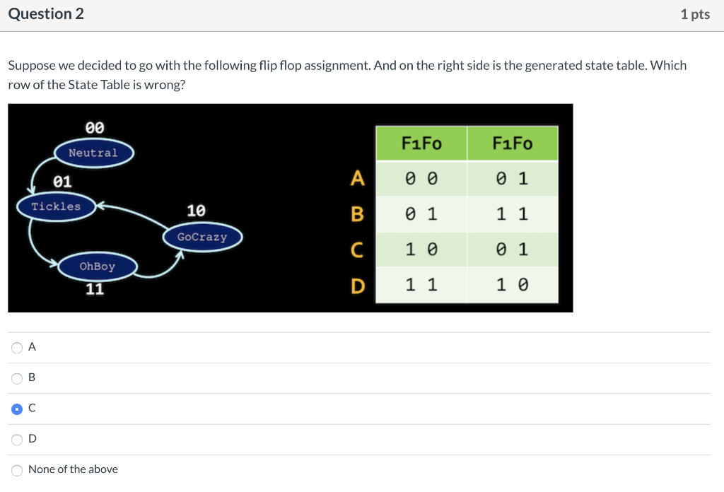
(2) Suppose we decided to go with the following flip flop assignment. And on the right side is the generated state table. Which row of the State Table is wrong?

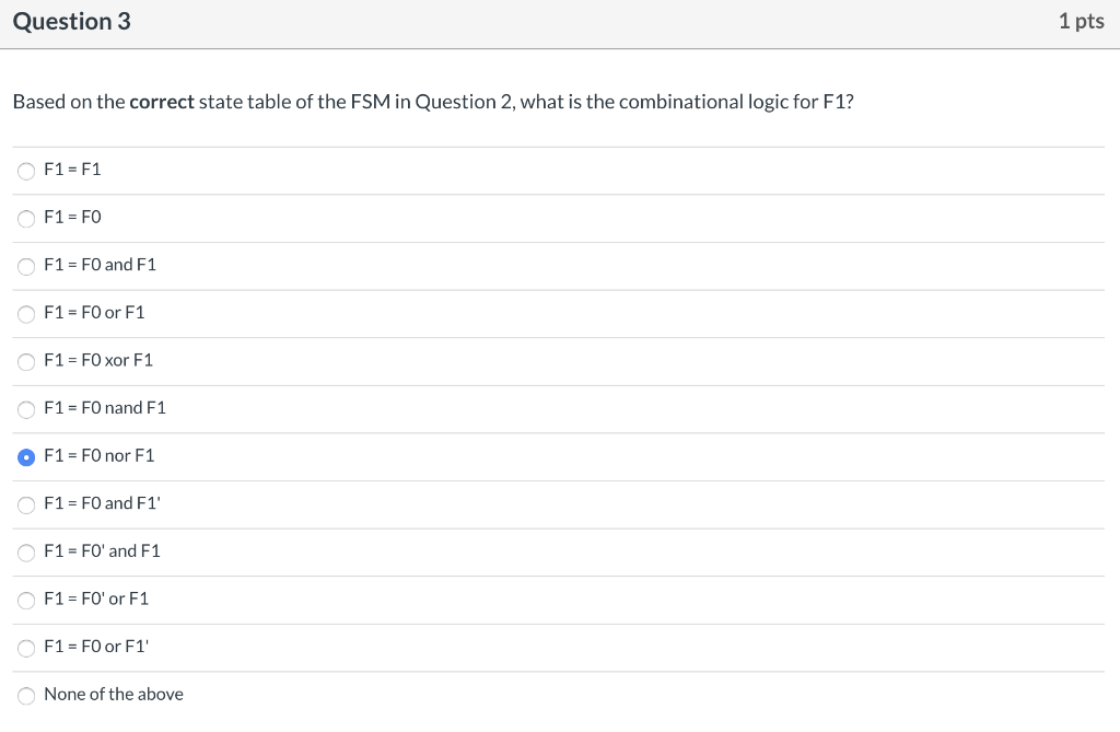
(3) Based on the correct state table of the FSM in Question 2, what is the combinational logic for F1?

(4) Based on the correct state table of the FSM in Question 2, what is the combinational logic for F0?

(5) Based on the correct combinational logic from Questions 3 and 4, connect the circuit in the following diagram so that the state transition diagram in Question 2 is implemented. Choose from below the wires that should be added to the circuit (indicated by pairs of pin names which are the red lower-case letters in the circuit diagram). You should choose exactly *four* wires and you'll get points for this question only if all four wires are chosen correctly. Use only the logic gates provided in the diagram, no other gate is allowed.


In the following questions, you will design the circuit of the Tickle Me Elmo... Below are two possible versions of the state transition diagram of Elmo, with two different ways of assigning flip-flop values. Which one of the transitions (A-H) will cause unexpected behaviour that cannot be completely avoided? 00 011 Neutral E Neutral (110 01 Tickles D 10 Tickles 000 GoCrazy GoCrazy OhBoy OhBoy 101 11 O A OB oc OF OH Question 2 1 pts Suppose we decided to go with the following flip flop assignment. And on the right side is the generated state table. Which row of the State Table is wrong? 00 Neutral 01 Tickles 10 F1F0 F1FO 00 01 B 01 1 1 10 01 11 10 GoCrazy OhBoy 11 OB oc OD None of the above Question 3 1 pts Based on the correct state table of the FSM in Question 2, what is the combinational logic for F1? F1 = F1 O F1 = FO F1 = FO and F1 O F1 = FO or F1 O F1 = FO xor F1 O F1 = FO nand F1 F1 = FO nor F1 F1 = FO and F1' F1 = FO' and F1 F1 = FO' or F1 F1 = FO or F1 None of the above Question 4 1 pts Based on the correct state table of the FSM in Question 2, what is the combinational logic for FO? FO = F1 FO = FO FO = FO and F1 FO = FO or F1 O FO = FO xor F1 OFO = FO nand F1 FO = FO nor F1 FO=FO and F1' FO = FO' and F1 FO=FO' or F1 O FO = FO or F1' None of above Question 5 1 pts Based on the correct combinational logic from Questions 3 and 4, connect the circuit in the following diagram so that the state transition diagram in Question 2 is implemented. Choose from below the wires that should be added to the circuit (indicated by pairs of pin names which are the red lower- case letters in the circuit diagram). You should choose exactly *four* wires and you'll get points for this question only if all four wires are chosen correctly. Use only the logic gates provided in the diagram, no other gate is allowed. HD QEb FO e-DQ9 1 F1 Squeeze (a,g) (ak) C (ai) (ap) (az) (b, e) (b, i) (bk) (bn) (b,x) (cm) (ci) Clej) (h, n) (hj) (g.j) (g,m) (gy) In the following questions, you will design the circuit of the Tickle Me Elmo... Below are two possible versions of the state transition diagram of Elmo, with two different ways of assigning flip-flop values. Which one of the transitions (A-H) will cause unexpected behaviour that cannot be completely avoided? 00 011 Neutral E Neutral (110 01 Tickles D 10 Tickles 000 GoCrazy GoCrazy OhBoy OhBoy 101 11 O A OB oc OF OH Question 2 1 pts Suppose we decided to go with the following flip flop assignment. And on the right side is the generated state table. Which row of the State Table is wrong? 00 Neutral 01 Tickles 10 F1F0 F1FO 00 01 B 01 1 1 10 01 11 10 GoCrazy OhBoy 11 OB oc OD None of the above Question 3 1 pts Based on the correct state table of the FSM in Question 2, what is the combinational logic for F1? F1 = F1 O F1 = FO F1 = FO and F1 O F1 = FO or F1 O F1 = FO xor F1 O F1 = FO nand F1 F1 = FO nor F1 F1 = FO and F1' F1 = FO' and F1 F1 = FO' or F1 F1 = FO or F1 None of the above Question 4 1 pts Based on the correct state table of the FSM in Question 2, what is the combinational logic for FO? FO = F1 FO = FO FO = FO and F1 FO = FO or F1 O FO = FO xor F1 OFO = FO nand F1 FO = FO nor F1 FO=FO and F1' FO = FO' and F1 FO=FO' or F1 O FO = FO or F1' None of above Question 5 1 pts Based on the correct combinational logic from Questions 3 and 4, connect the circuit in the following diagram so that the state transition diagram in Question 2 is implemented. Choose from below the wires that should be added to the circuit (indicated by pairs of pin names which are the red lower- case letters in the circuit diagram). You should choose exactly *four* wires and you'll get points for this question only if all four wires are chosen correctly. Use only the logic gates provided in the diagram, no other gate is allowed. HD QEb FO e-DQ9 1 F1 Squeeze (a,g) (ak) C (ai) (ap) (az) (b, e) (b, i) (bk) (bn) (b,x) (cm) (ci) Clej) (h, n) (hj) (g.j) (g,m) (gy)


