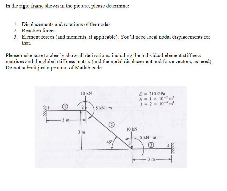
In the rigid frame shown in the picture, please determine: 1. Displacements and rotations of the nodes 2. Reaction forces 3. Element forces (and

In the rigid frame shown in the picture, please determine: 1. Displacements and rotations of the nodes 2. Reaction forces 3. Element forces (and moments, if applicable). You'll need local nodal displacements for that. Please make sure to clearly show all derivations, including the individual element stiffness matrices and the global stiffness matrix (and the nodal displacement and force vectors, as need). Do not submit just a printout of Matlab code. 10 kN 3 m 3 m E = 210 GPa A = 1 x 10⁻² m 1 = 2 10-4 m 5 kN m 10 kN 5 kNm 45% 3 3 m
Step by Step Solution
There are 3 Steps involved in it
Step: 1
Solutions Step 1 Given Data E210GPa A1102 m2 I2104 m4 Loads and geometry as shown in the figure Intr...
See step-by-step solutions with expert insights and AI powered tools for academic success
Step: 2

Step: 3

Ace Your Homework with AI
Get the answers you need in no time with our AI-driven, step-by-step assistance
Get Started


