

Answered step by step
Verified Expert Solution
Question
1 Approved Answer
In the setup shown in the figure, Vref average is set to 2 v, but the wheel has been stopped by hand. what are the
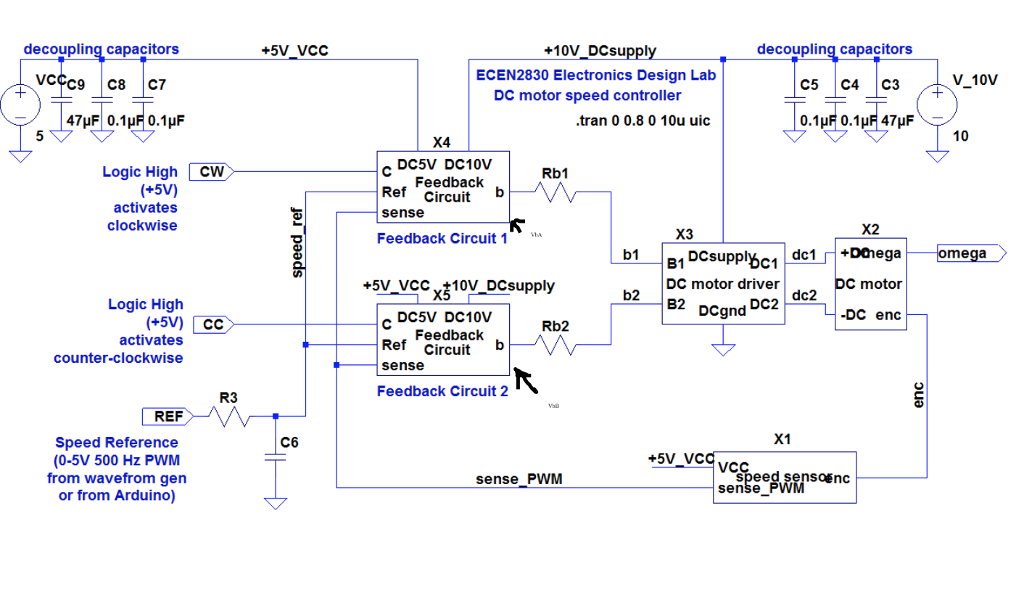
In the setup shown in the figure, Vref average is set to 2 v, but the wheel has been stopped by hand. what are the following voltages?
Average of sense_PWM=
VbB=
VbA=
explain
decoupling capacitors +5V VCC +10V DCsu decoupling capacitors ECEN2830 Electronics Design Lab C5 C4 C3 V 10V DC motor speed controller tran 0 0.8 0 10u uic 10 X4 DC5V DC10V Logic High CW Rb1 Feedback (+5V) activates clockwise Ref Circuit sense Feedback Circuit 1 . X2 X3 b11DCsupphhc1 mega DC motor driver C motor Logic High DCgnd Dc2 dc2 -DC end DC5V DC10V Ref Circuit sense Feedback Circuit 2 (+5V) CC Feedbackb Rb2 activates counter-clockwise R3 REF X1 Speed Reference (0-5V 500 Hz PWM from wavefrom gen or from Arduino) C6 +5V VC sense PWM SOEnC sense decoupling capacitors +5V VCC +10V DCsu decoupling capacitors ECEN2830 Electronics Design Lab C5 C4 C3 V 10V DC motor speed controller tran 0 0.8 0 10u uic 10 X4 DC5V DC10V Logic High CW Rb1 Feedback (+5V) activates clockwise Ref Circuit sense Feedback Circuit 1 . X2 X3 b11DCsupphhc1 mega DC motor driver C motor Logic High DCgnd Dc2 dc2 -DC end DC5V DC10V Ref Circuit sense Feedback Circuit 2 (+5V) CC Feedbackb Rb2 activates counter-clockwise R3 REF X1 Speed Reference (0-5V 500 Hz PWM from wavefrom gen or from Arduino) C6 +5V VC sense PWM SOEnC senseStep by Step Solution
There are 3 Steps involved in it
Step: 1

Get Instant Access to Expert-Tailored Solutions
See step-by-step solutions with expert insights and AI powered tools for academic success
Step: 2

Step: 3
Ace Your Homework with AI
Get the answers you need in no time with our AI-driven, step-by-step assistance
Get Started
Database Systems For Advanced Applications 9th International Conference Dasfaa 2004 Jeju Island Korea March 2004 Proceedings Lncs 2973
Authors: YoonJoon Lee ,Jianzhong Li ,Kyu-Young Whang
2004th Edition